TITAN
™
Code Compliant Modular Access System Installation Manual
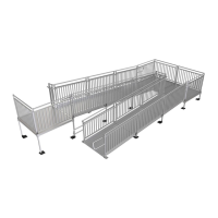
3.3.9. Use hole in the foot as a template to drill an 11/32” or 3/8” hole through each
support leg (FIG 3.9).
3.3.10. Insert a 5/16”-18 x 3” long hex bolt through the support leg and foot. Secure with
5/16”-18 nylon insert locknut.
FIG. 3.9
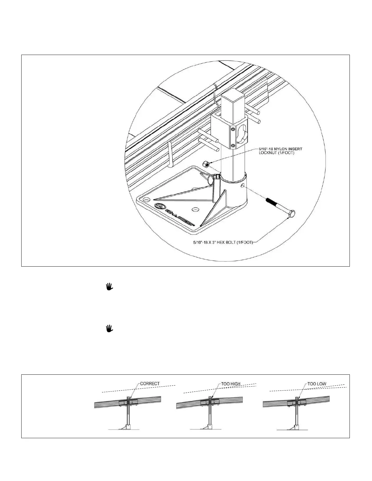
3.3.11. Adjust the ramp support legs one at a time.
Building codes and ADA guidelines call for a maximum slope of 1:12. This is also
the required slope for the TITAN system.
3.3.11.1. Raise (or lower) the ramp sections at the center saddle bracket to take
any sag out of the ramp run. Loosen and retighten the two set screws
in each support leg bracket to 15 ft.-lbs. as needed.
Adjustment can be accomplished by having someone sight down the ramp while
another person adjusts the ramp height or by using a straight string line.
3.3.12. Ensure that all bolts and set screws are fully tightened as specified.
3.3.13. Ensure that the ramp sections are aligned parallel, on the same plane, to one another
(FIG 3.10).
FIG. 3.10
 Loading...