Table 10. LCM, CAN1, CAN2 port
:
PIN number and signal description
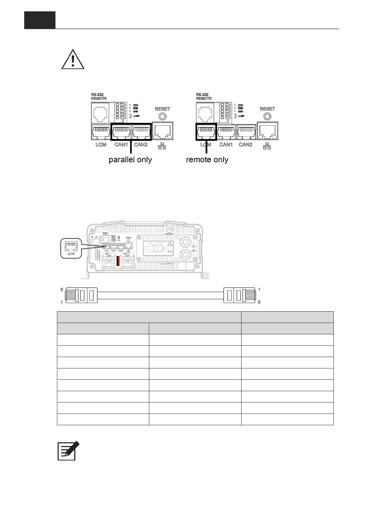
WARNING!
LCM port is designed for connect remote only.
To use CAN1 and CAN2 for parallel connection, please do not plug in LCM.
3-13. LCM Port
Connection for LCD remote control panel, you can set and display the ECB-series
operation status.
Figure 9. LCM port
Figure 10. LCM cable
Table 11. PIN number and signal description for LCD remote control
Note
The cables should be as short as possible (less than 32.8 feet / 10 meters) so
that they can handle the signal.