33 Dokument-Nr.: 01.1411.010.71e / Revision: 3.00
4.7 Wiring
4.7.1 Conductor Cross Section
Power Supply (Power, GND): AWG18 (0.96 mm²)
Signals: AWG22 (0.38 mm²)
The conductors used must be approved for aircraft installation.
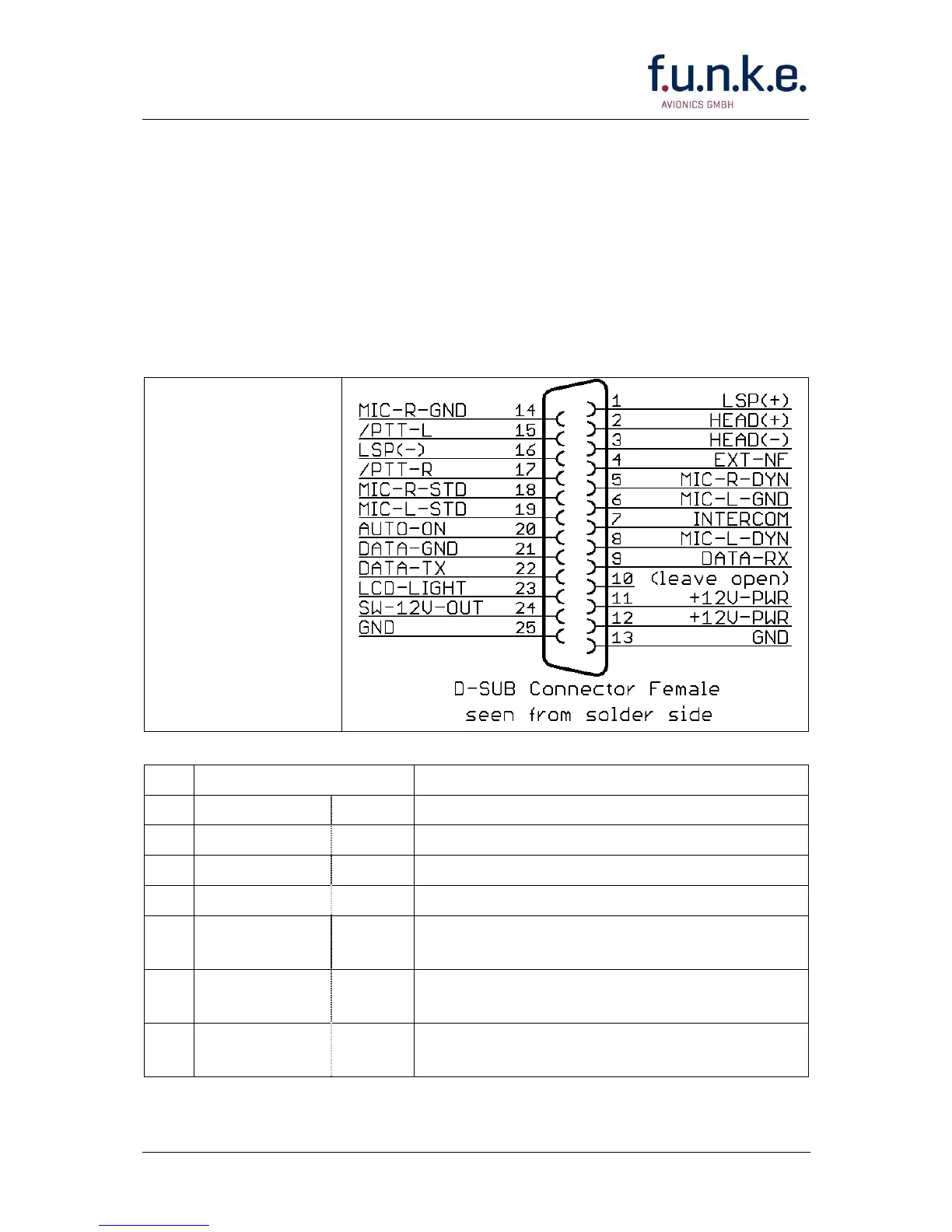
4.7.2 Connector – Pin Allocation
SSATR2
25-pin connector at
the ATR833A
View from
aircraft’s side
Pin
Names Functionality
1 LSP(+) LSP+ Output external Loudspeaker Positive
2 HEAD(+) HSP+ Output Headset-Speaker Positive
3 HEAD(−) HSP− Output Headset-Speaker Negative
4 EXT-NF Input external Audio-Signal
5 MIC-R-DYN MRD+ Input dynamic Microphone
(Glider/Gooseneck) Copilot/Right
6 MIC-L-GND MLS−
MLD−
Ground for Microphones Pilot/Left
7 INTERCOM ICS Intercom Activation Switch (connect to
ground for activation of intercom)