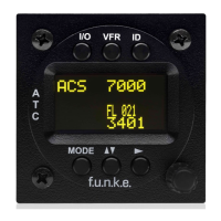
TRT800H / P/N 800ATC-H-(2xx)-(2xx)
Operation and Installation
Document-No: 03.2124.010.71e / Revision: 2.10
The transponder may only be operated together with an
external memory address adaptor TRT800EMxx
Adaptor
Typ
(4)
TRT800
EMSS
● = in the plug and get out ○ = in the plug and not get out
∕ = internal connection to the device
SWITCHED +UB
OUT, Interface
Remote control
May only be used for compatible f.u.n.k.e. AVIONICS
devices. Do not connect pins if interface is not used.
Connect to +UB override front panel on/off button. Leave
unconnected to use front panel on/off button.
If an external Ground Switch is connected, it must
connect this pin to GND to indicate the on-ground
condition. Leave open otherwise.
Adaptors
TRT800EM &
TRT800EMSS
Adaptor version does not provide full interface capability
(see table for details).