TRT800H / P/N 800ATC-H-(2xx)-(2xx)
Operation and Installation
Document-No: 03.2124.010.71e / Revision: 2.10
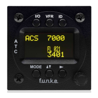
3.10 Starting Up
Turn the transponder on with I/O. After start-up the following screens
appear:
3.11 Accessories
Antenna cable 1,0 m (3.2 ft) TNC BNC
Antenna cable 2,5 m (8.2 ft) TNC BNC
Antenna cable 4,0 m (13.2 ft) TNC BNC
Antenna cable 6,5 m (21.3 ft) TNC BNC
External-Memory (Aircraft-Address-Adaptor)
Connection cable with interface TRT-Remote control
Transponder/DME Antenna TSO C66b, C74c
CI105 Comant Industries Inc.
Height: 3,25”, Weight: 90 g (0.2 lbs)
Transponder Rod antenna TSO C74c
AV-22 R A Miller Industries
The TRT800H starts in standby mode (indicated with
STBY). In order to change into operational mode (indicated
with ACS) press MODE . If ground switch is connected
and status “in flight” is selected TRT800H starts in active
mode.
Very important is the correct configuration of the 24bit
Aircraft-Address (see 4.5.4 General Setup).
TRT800H
V5.3
FPGA-Vers: 102