When both the ANALOG OUTPUT and AUTO RANGE features are active, the following condition can occur:
Suppose the present range is 3 kG and the present reading is +2.8 kG. The analog output will be +2.8 VDC. The signal then increases to +3.2
kG, which would force an automatic change to the 30 kG range setting. The analog output will now be +0.32 VDC because of the range
change. This can lead to problems if the analog signal is being used to make decisions since there is no indication that a range change has
occurred. In these situations, it is best to select a fixed range that covers the expected flux density span.
The analog output signal contains both the DC and AC components of the flux density signal. This means that it will also contain any initial DC
offsets in the probe and the meter’s circuitry. These offsets can be removed by the ZERO function.
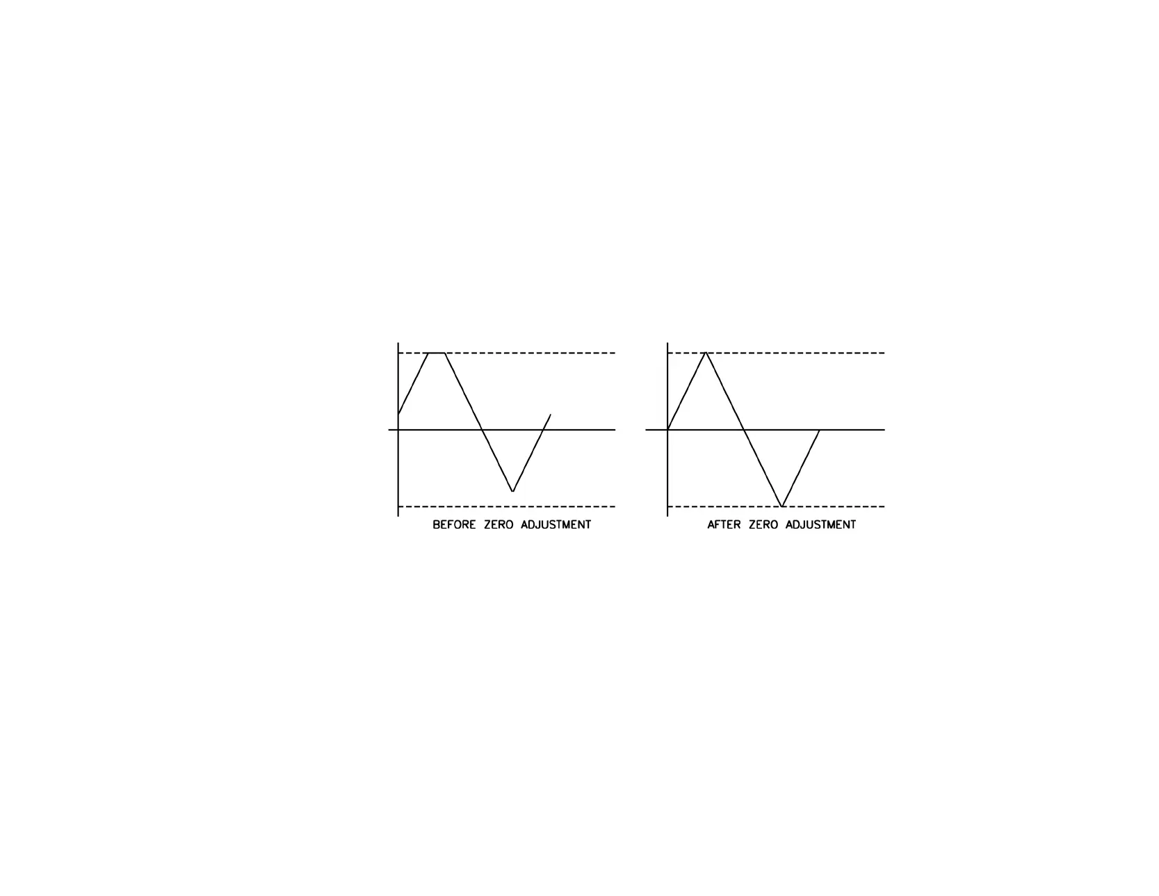
The ZERO function can also be used to introduce a DC offset if desired. This is useful when observing AC waveforms in which one portion of
the waveform is being clipped because it exceeds the 4.25 VDC limit of the meter. Using the ZERO function, the center of the waveform can
be moved to reduce or eliminate the "clipping" as depicted in the figure below.
Adjusting the DC Offset of the Analog Output
 Loading...