Introduction
MEASUREMENT OF FLUX DENSITY
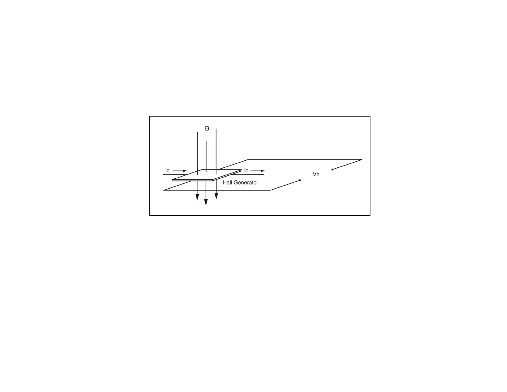
A device commonly used to measure flux density is the Hall generator. A Hall generator is a thin slice of a semiconductor material to which
four leads are attached at the midpoint of each edge, as shown in Figure 1-2.
A constant current (Ic) is forced through the material. In a zero magnetic field, there is no voltage difference between the other two edges.
When flux lines pass through the material, the path of the current bends closer to one edge, creating a voltage difference known as the Hall
voltage (Vh). In an ideal Hall generator, there is a linear relationship between the number of flux lines passing through the material (flux
density) and the Hall voltage.
The Hall voltage is also a function of the direction in which the flux lines pass through the material, producing a positive voltage in one
direction and a negative voltage in the other. If the same number of flux lines pass through the material in either direction, the net result is zero
volts. This sensitivity to flux direction makes it possible to measure both static (dc) and alternating (ac) magnetic fields.
The Hall voltage is also a function of the angle at which the flux lines pass through the material. The greatest Hall voltage occurs when the flux
lines pass perpendicularly through the material. Otherwise, the output is related to the cosine of the difference between 90º and the actual
angle.
Figure 1-2
Hall Generator
 Loading...