The sensitive area of the Hall generator is generally defined as the largest circular area within the actual slice of the material. This active area
can range in size from 0.2 mm (0.008”) to 19 mm (0.75”) in diameter. Often the Hall generator assembly is too fragile to use by itself so it is
often mounted in a protective tube and terminated with a flexible cable and a connector. This assembly, known as a Hall probe, is generally
provided in two configurations:
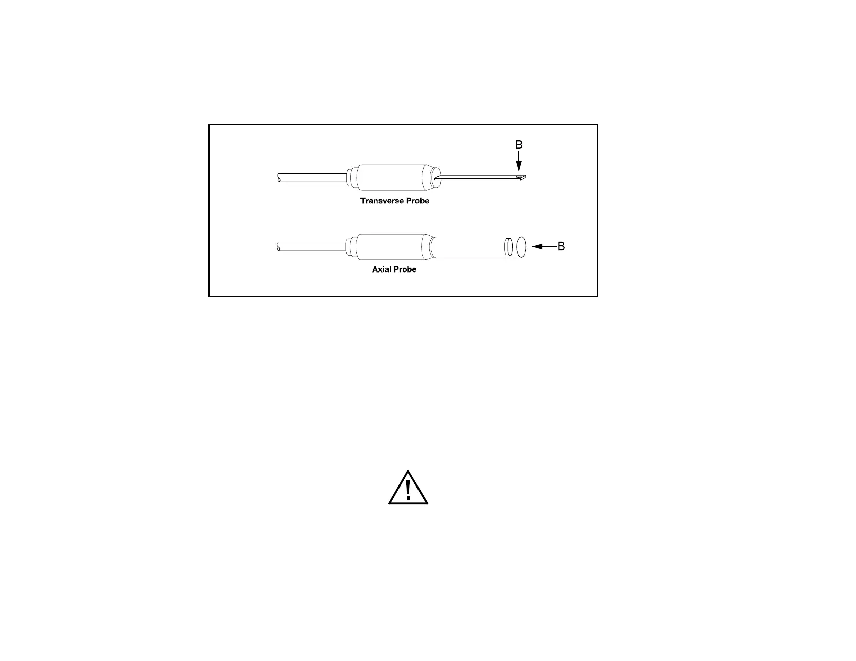
In “transverse” probes, the Hall generator is mounted in a thin, flat stem, whereas in “axial” probes the Hall generator is mounted in a
cylindrical stem. The axis of sensitivity is the primary difference, as shown by “B” in Figure 1-3. Generally, transverse probes are used to make
measurements between two magnetic poles such as those in audio speakers, electric motors and imaging machines.
Axial probes are often used to measure the magnetic field along the axis of a coil, solenoid or traveling wave tube. Either probe can be used
where there are few physical space limitations, such as in geomagnetic or electromagnetic interference surveys.
Figure 1-3
Hall Probe Configurations
Handle the Hall probe with care. Do not bend the stem
or apply pressure to the probe tip as damage may
result. Use the protective cover when the probe is not
in use.
 Loading...