40
For extra-European countries where the EN16005 standard is not in force, it is possible to continue
using photocells and traditional sensors.
Warning : photocells are not permitted as a safety device in the countries of the European community
where the EN16005 standard is in force Specifically, photocells are considered as auxiliary devices, com-
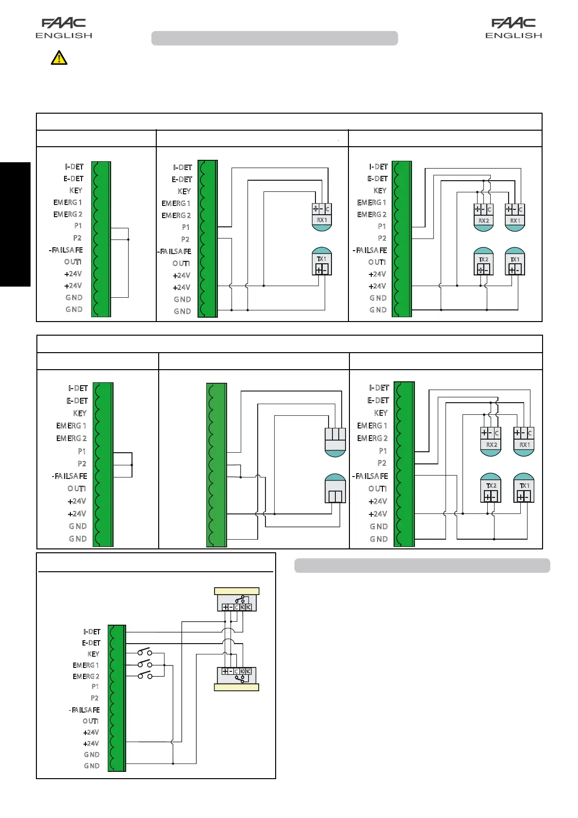
plementary to safety. Below are the connections on automatic door board:
Connection terminal J7
PHOTOCELLS
Two types of photocells can be connected to the door: the
traditional ones to be connected to connector J7 (inputs P1 and P2
with N.C. or N.O. contact ) and those with a button for connection
to connector J4. The following configurations are possible if using
traditional photocells:
NO PHOTOCELL
• In the standard configuration, P1 and P2 inputs must be jumper
connected to the FAIL-SAFE terminal;
• fortheDisplay,asanalternative,theP1andP2inputscanbe
disabled, thus avoiding the jumpers.
1 PHOTOCELL
• In the standard configuration, the photocell must be connected
to the P1 input, while P2 must be jumper connected to the FAIL-
SAFE terminal;
• fortheDisplay,asanalternative,onephotocellonlycanbeset
(connecting it to the P1 input as usual), thus disabling the P2
input and avoiding the jumper .
2 PHOTOCELLS
• connect the photocells to the P1 and P2 inputs.
CONNECTION OF PHOTOCELLS WITH FAIL-SAFE DISABLED
no photocell
1 pair of photocells
2 pairs of photocells
CONNECTION OF PHOTOCELLS WITH FAIL-SAFE ENABLED
no photocell
1 pair of photocells
2 pairs of photocells
TERMINAL BOARD J7
1
2
3
4
5
6
7
8
9
10
11
12
13
I-DET
E-DET
KEY
EMERG 1
EMERG 2
P1
P2
- FA I LS A F E
O UT1
+24V
+24V
G ND
G ND
+
-
C
+
-
TX 1
RX1
1
2
3
4
5
6
7
8
9
10
11
12
13
I-DET
E-DET
KEY
EMERG 1
EMERG 2
P1
P2
- FA I LS A F E
O UT1
+24V
+24V
G ND
G ND
1
2
3
4
5
6
7
8
9
10
11
12
13
+
-
C
+
-
+
-
C
+
-
TX 1
RX1
TX 2
RX2
I-DET
E-DET
KEY
EMERG 1
EMERG 2
P1
P2
- FA I LS A F E
O UT1
+24V
+24V
G ND
G ND
1
2
3
4
5
6
7
8
9
10
11
12
13
J7
I-DET
E-DET
KEY
EMERG 1
EMERG 2
P1
P2
O UT1
+24V
+24V
G ND
G ND
1
2
3
4
5
6
7
8
9
10
11
12
13
+
-
C
+
-
+
-
C
+
-
TX 1
RX1
TX 2
RX2
I-DET
E-DET
KEY
EMERG 1
EMERG 2
P1
P2
- FA I LS A FE
O UT1
+24V
+24V
G ND
G ND
1
2
3
4
5
6
7
8
9
10
11
12
13
+
-
C
+
-
TX1
RX1
I-DET
E-DET
KEY
EMERG1
EMERG2
P1
P2
OUT1
+24V
+24V
GND
GND
-FAILSAFE
1
2
3
4
5
6
7
8
9
10
11
12
13
+ -
C
+ -
C
J7
I-DET
E-DET
KEY
EMERG 1
EMERG 2
P1
P2
-FAILSAFE
O UT1
+24V
+24V
G ND
G ND
INTERNAL SENSOR
EXTERL SENSOR
 Loading...