3
a
b
c
d
e
f g
h
MODEL A140 AIR A140 AIR 2
No.ofleaves 1 2
Maxleafweight 200Kg 120+120Kg
T
ransit
space(VP) 700 ÷ 3000 mm 800÷3000mm
Maxthicknessofframedleaf 65mm
Usefrequency 100 %
Protectionclass IP23(forindooruse)
Operatingambienttemperature -20°C÷+55°C
P
ower
supply 115V/230V~50/60Hz
Maxabsorbedpower 100 W
Beamlength Vpx2+100mm
Driveunit 24Vdcwithencoder
Openingspeedadjustment(loadfree) 5÷70cm/sec
. 10
÷140cm/sec
.
Closing
speedadjustment(loadfree) 5÷70cm/sec
. 10
÷140cm/sec
.
Partial
openingadjustment 10%÷90%oftotalopening
Pause time adjustment 0÷30sec
.
Night
pausetimeadjustment 0÷240sec
.
Static
forceadjustment automatic
Anti-crushingdeviceactive atopening/closing
F
ailsafe
onphotocells Yes(canbeactivatedbyprogramming)
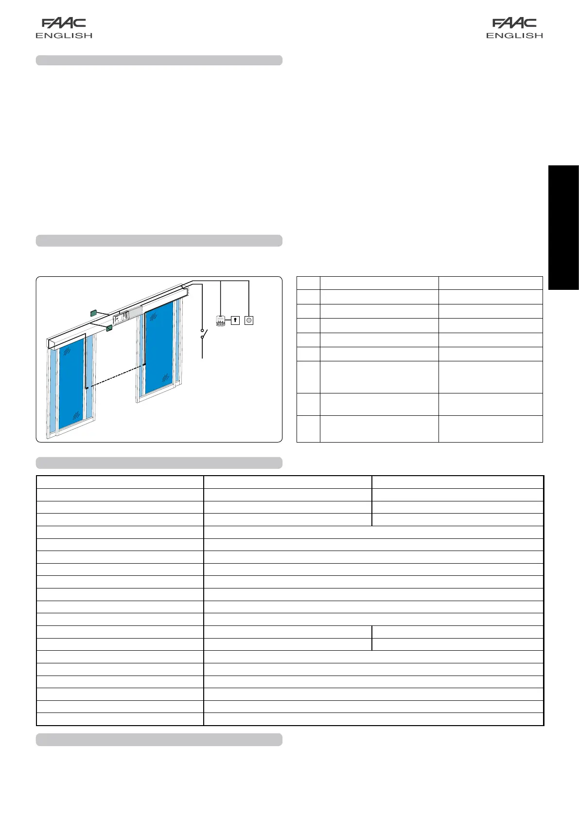
2 ELECTRICAL PREPARATIONS
3 TECHNICAL SPECIFICATIONS
Routetheelectricalcablesforconnectingtheaccessoriesand
electricalpowersupplyasshowninFig.2.
N° DESCRIPTION CABLES
a
External radar 4x0.25mm²
b
Internal radar 4x0.25mm²
c
Photocell transmitter 2x0.25mm²
d
Photocell receiver 3x0.25mm²
e
SD-Keeper / SDK-Light 2x0.5mm² max 50 m
f
Keyoperatedswitch
forlockingSD
-Keeper
/
SDK
-Light
(futureaccessor
y)
2x0.5mm²
g
Control push-buttons
Emerg/Key/Reset
2x0.5mm²
h
Power supply
115/230V
~
2x1.5mm² + earth
1.2 DOOR FRAME ACCESSORIES
To facilitate the door profile to adapt to the carriages and to enable correct finish of the installation, FAAC offers the following
series of articles:
Pair of sliding blocks (fig. 24-25 ref. a)
Supplied as a pair, they can be secured on a wall (or on the fixed leaf) or directly on the floor.
Lower guide profile (fig. 24-25 ref. b)
For adapting the lower profile of the leaf to the above sliding blocks.
Brush for lower guide profile (fig. 24-25 ref. c)
Completes the on-floor guide system.
Leaf fitting profile (fig. 17-18 ref. a)
Adapts the leaf’s top profile to the carriage fittings.
Pair of lower sliding blocks for glass panel leaf
They enable the glass leaves to slide
4 CROSS BEAM CONFIGURATION
To suitably position the cross beam components, refer to the
dimensions in figures 7, 8, and 9.
fig. 2