2
h
b
c
d
e
f
g
a
i
l
j
k
AUTOMATIC DOOR A140 AIR H100 - H140
1 DESCRIPTION
The FAAC series A140 AIR systems automatically activate,
manage and control the operation of single-leaf or two-leaf
slidingdoors.
The FAAC series A140 AIR automated systems are supplied
completely assembled, wired and tested in the configuration
requestedbythecustomer,usingtheappropriateorderform,or
inkitstobeassembledbytheinstallationtechnician.
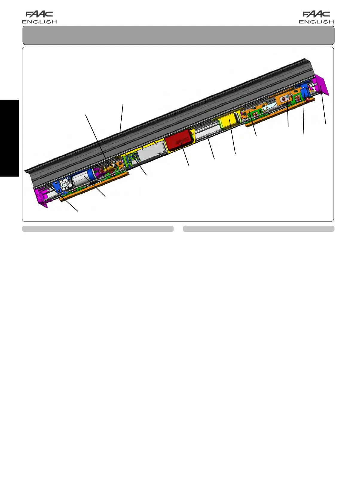
An automation cross beam (fig.1) consists of the following
parts:
Support profile(fig.1ref.a)
Thisistheprofileusedwhenthecrossbeamcanbecompletely
securedtoaloadbearingstructure.
Motor unit (fig.1ref.b)
The 24= motor has an encoder and a leaf locking system
(accessory).
The Electronics Module includes:
Control unit (fig.1ref.c)
Whenpowered,thecontrolunitwithmicroprocessor,initialises
thedoor’soperationalparameters.
Power feed unit (fig.1ref.d)
Thepowerfeedunit,directlyconnectedtothecontrolunit,
suppliesthevoltagevaluesrequiredtocorrectlypowerthe
automatedsystem.
Leaf support carriages(fig.1ref.e)
Thecarriageshavetwowheelswithballbearings,onecounter
thrust wheel in the top part, and a screw based system for
adjustingtheheightoftheleaves.
Drive belt(fig.1ref.f)
Transmission pulley unit(fig.1ref.g)
1.1 ACCESSORIES SUPPLIED WITH THE CROSS BEAM
Thesepartsareassembledonthecrossbeam.
Closing housings (fig.1ref.h)
Thisisthealuminiumprofileenablingclosureoftheautomated
system. The side panels (fig.1 ref.k) completely close the
system.
Motor lock unit (fig.1ref.i)
Themotorlockunitguaranteesmechanicallockingofthedoor
whiletheleavesareclosed.Themotorlockunitcanbeusedfor
singleanddoubleleaves.
Themotorlockunitissuppliedwiththeinternalreleasedevice
(Fig.1ref.j)usedforemergencyopeningifneeded.Itisalso
designed for installation of the external release (optional) if
required.Themotorlockunitactsdirectlyonthemotor,locking
itmechanically.
Supervision of motor lock
Itcontrolsifthemotorlockunitisoperatingcorrectlyandverifies
ifthedoorisactuallyclosed.Ifnecessary,thesystemisdesigned
forremotelyactivatinganindicatorlightorbuzzer/siren.
Emergency battery(fig.1ref.l)
Intheeventofamainspowercut,thebatterykitenablesthe
automatedsystemtooperateuntilitschargeisexhausted.The
batteryconditiontestisperformedcontinuouslybythecontrol
unit.
fig. 1