16
a
b
a
b
c
b
a
c
c
e
a
b
d
c
c
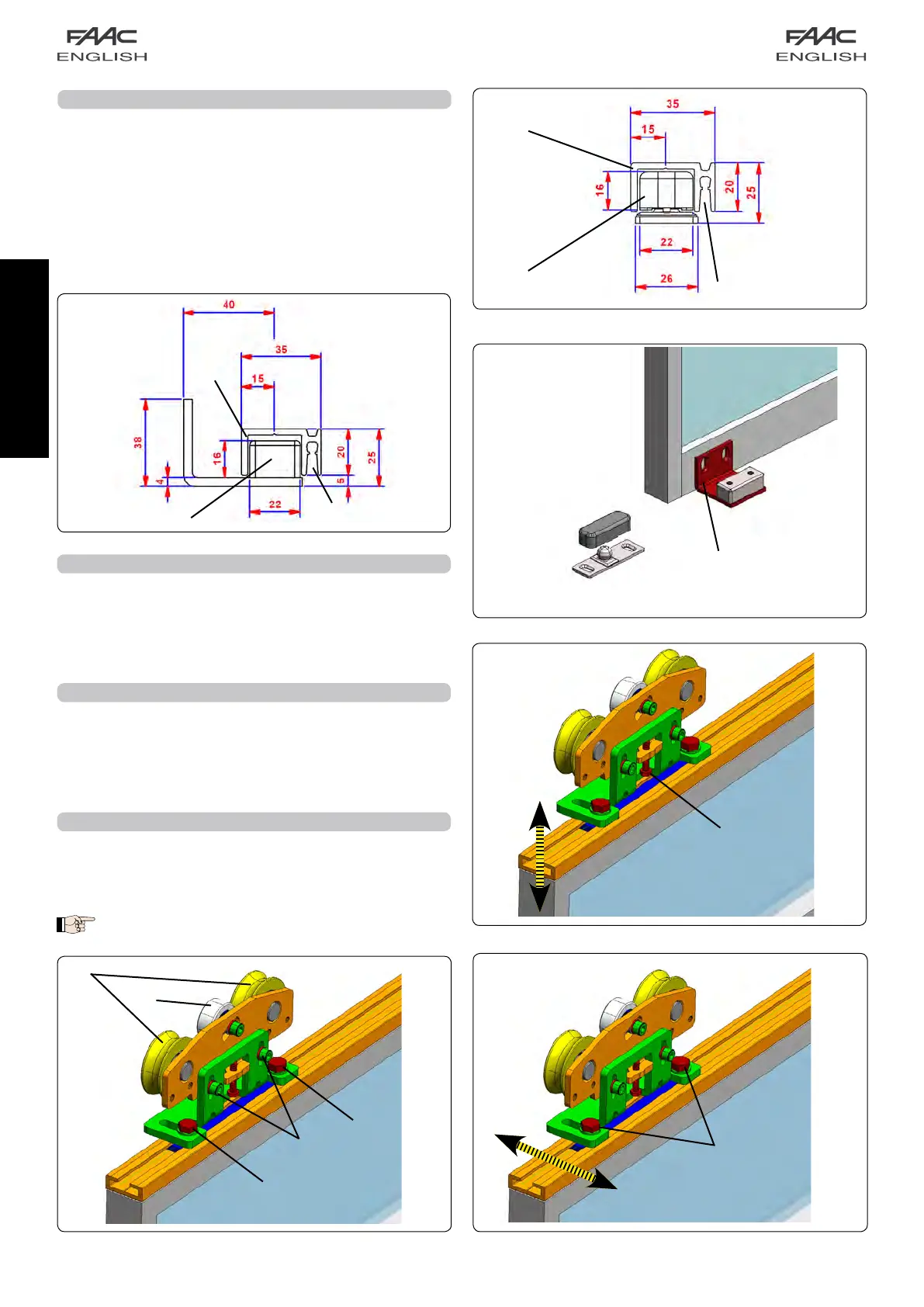
The carriages allow leaf height adjustment of ± 7.5 mm.
Adjustmentprocedure:
• SlightlyloosenthetwoscrewsM6-fig.28ref.d.
• Turnthescrew(fig.27ref.5clockwisetoraisetheleavesoranti-
clockwisetolowerthem.
• TightenthetwoscrewsM6youhadloosened
4.1A LEAF HEIGHT ADJUSTMENT
4A ADJUSTING THE LEAVES
Whenyouhavepreparedtheleaves,installthemonthesupport
profile.
The carriages have two sliding wheels (Fig.28 ref. a) and a
counter-thrustwheel(Fig.28ref.b)
Twoslotsareprovidedonthebaseofthecarriages.Theseslots
enableleafdepthadjustment(Fig.28ref.c)
4.2A LEAF DEPTH ADJUSTMENT
Toadjustthedepthoftheleaves,loosenthe2boltsasshownin
Fig.29rif.
c
.
Movetheleafonthecarriageslotasyourequireandtightenthe
2bolts.
Make sure that the leaves are parallel with respect
to the support profile.
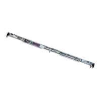
3A INSTALLING THE LOWER SLIDING BLOCKS
The lower sliding blocks are designed for securing to a wall (or
fixedleaf)ortothefloor.
Assembletheslidingblocks,referringtothedimensionsinfigures
24and25.
On-wall securing (or on fixed leaf):
• Secure the sliding blocks as shown in Fig. 26 ref.a, using
adequatescrews.
Securing on the floor
• Directlysecuretheslidingblocktothefloor,asshowninFig.26
ref.b,usingadequateexpansionplugsandscrews.
fig. 26
fig. 24
fig. 25
fig. 28
fig. 29
fig. 27
 Loading...