60
A
B
C
A
B
B
A
C
B
C
B
C
C
B
A
MOTOR LOCK SUPERVISION
This accessory (Fig. 51 ref. C) makes it possible to verify correct
operation of the motor lock and, if it stays locked while open,
signalsanerrorviathecontrolboardorSD-Keeper.
To activate motor lock surveillance, the function must be set with
thecontrolboardorSD-Keeper.
BATTERY KIT
Instructions to connect and install the battery kit:
• cut out mains power supply;
• insert the connector of the battery pack in connector J16
of board E100;
• power up the mains supply again;
• usingSD-Keeper+Display,activatethe“BatteryKit”andset
the operating parameters you require (refer to the dedicated
section in this manual);
IMPORTANT: TO AVOID DAMAGING THE BATTERY BOARD,
THE BATTERY BOARD MUST ALWAYS BE ACTIVATED AND
DISABLED WHILE NO MAINS POWER IS SUPPLIED
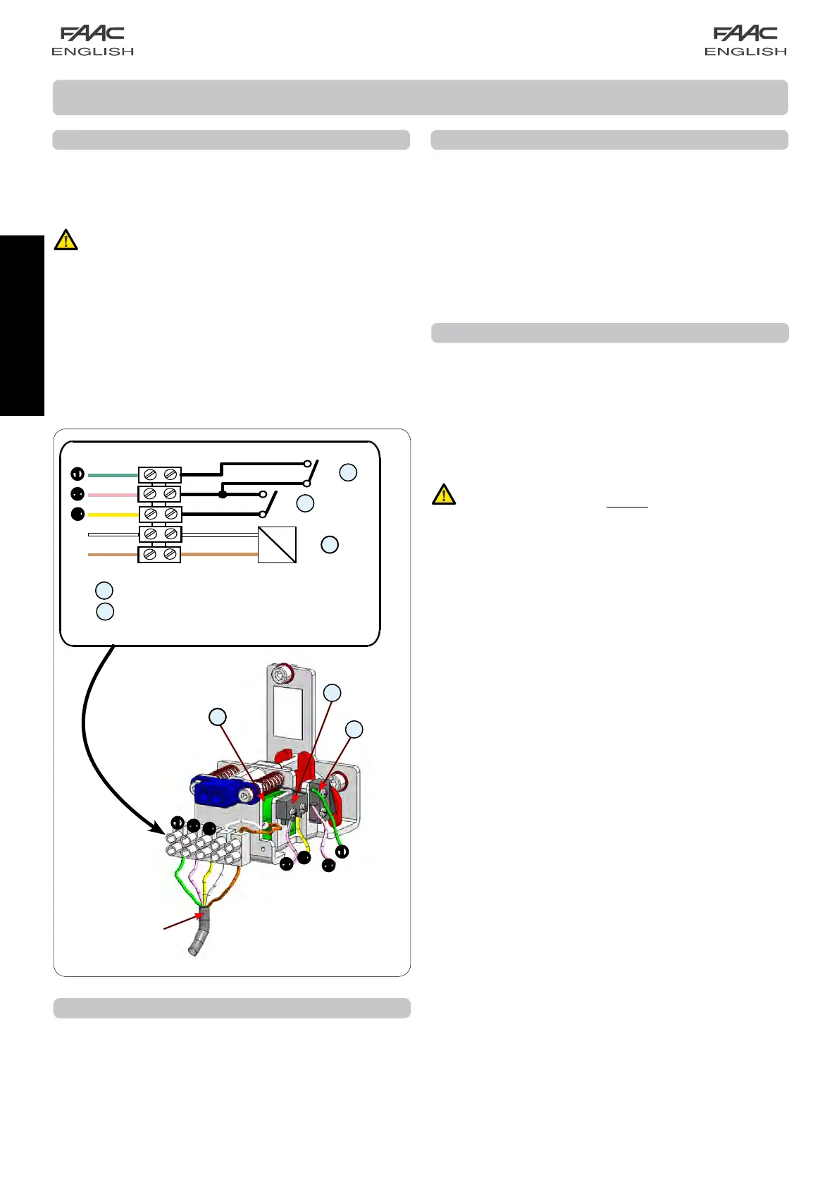
MOTOR LOCK
Motorlockinstallationprocedure:
• cut out mains power supply;
• connect the motor lock connector to J5 of board E100;
• power up.
TO AVOID DAMAGING THE MOTOR LOCK, ALWAYS
ACTIVATE OR DISABLE IT WHEN NO POWER IS SUPPLIED.
In the standard configuration:
The motor lock locks the leaves only in “Night” operating function;
- if operating on batteries in the Night mode, if the batteries
discharge, the motor lock continues to lock the leaves.
WithSD-Keeper+DisplayorE100,youcanchangetheoperation
of the motor lock.
ACCESSORIES
BROWN
BROWN
WHITE
YELLOW
WHITE
GREEN
PINK
Connect to J5
E100 board
motor lock release microswitch
motor lock monitoring microswitch
ANTI-PANIC BY BREAK-OUT
This accessory enables the leaves to be opened by pressure; to
install it, refer to the specific instructions.
If installing the anti-panic by break-out facility, a sensor or
photocell must be connected to the EMERG1 input (via SD-
Keeper+Display)configuredforcommandingimmediatestop
of the movement (STOP).
Connection of
microswitches
fig. 51
A
B
C