Mt740/745, 741/746/En/Rev. 002/12/97 * 901.742 002
BEISSBARTH MT 740/ 745, 741/ 746
4-5
UNI (universal) flanges are used to clamp wheels on to the wheel balancer in the case of all
closed-centre wheels with 3, 4 and 5-hole patterns as well as all wheels with unmachined centre
bores.
To avoid clamping errors as far as possible, the tyre valve must be in face-downward position
when clamping the wheel on to the flange and fitting to the car.
Make sure that the mounting nut directly located next to the valve is always tightened first; then
tighten all other nuts in a crosswise pattern.
When the balancing procedure has been completed, fit the wheel to the car according to the same
procedure.
9. Centring and mounting of the wheel with
locating pins and double-ended conical nuts or
quick-clamping cones:
Select required hole pitch circle pattern for the
hole centre plate of the flange and insert
correct number of locating pins.
Secure locating pins from back with knurled
nuts.
Carefully push wheel with mounting bores over
the locating pins and against the mounting
surface of the flange.
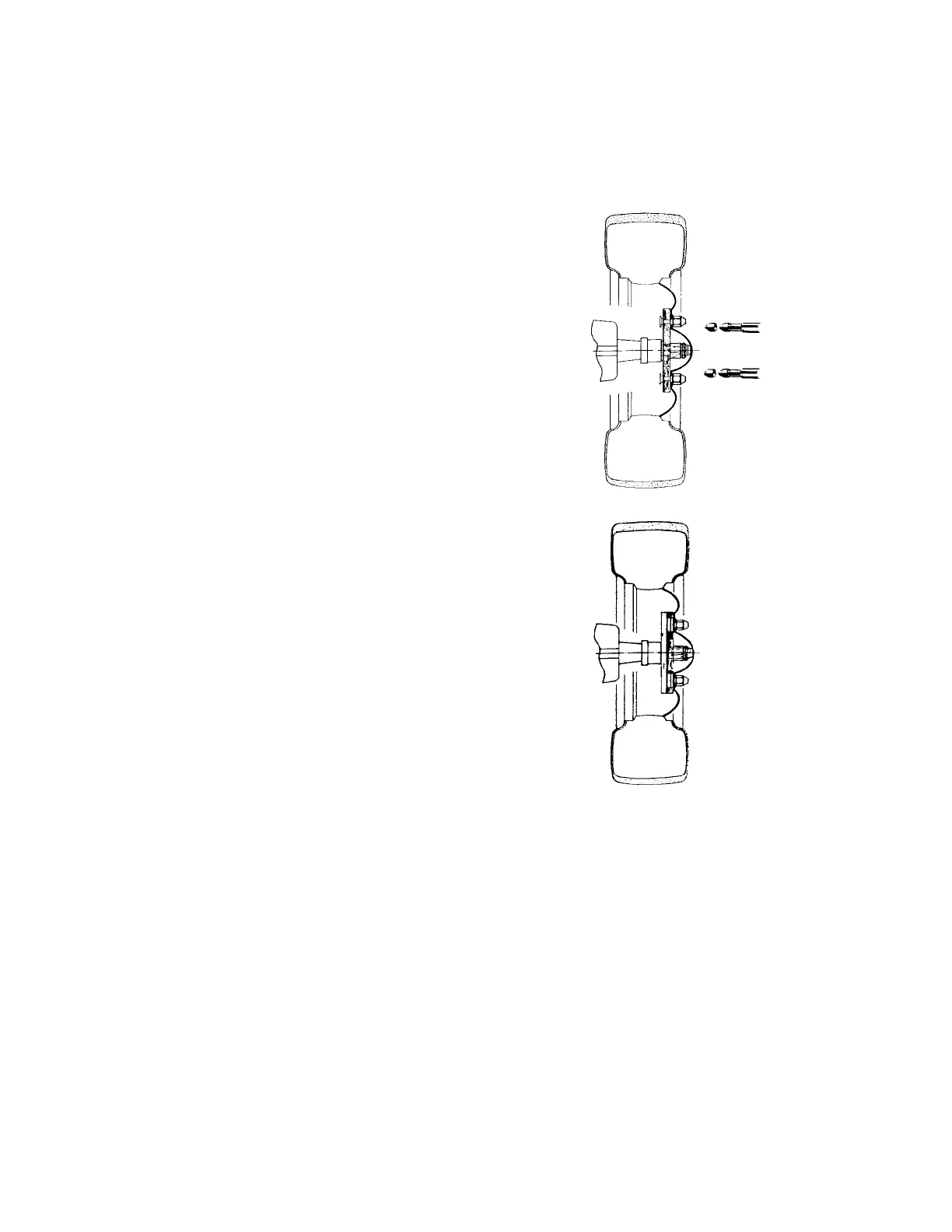
Tighten double- ended conical nuts on the
locating pins with box wrench 22 mm across
flats or use quick -clamping cones (see Figure 9).
10. Centring and mounting of the wheel with
sliding bolts and double-ended conical nuts or
quick-clamping cones:
Insert required sliding bolts into the flange
guides and adjust to the desired hole circle
pattern.
The sliding bolts are set via ball-grids to the
selected hole circle.
The wheel is mounted on to the flange as
described under Item 9 (see Figure 10).
11. Centring and mounting of wheel with steplessly
adjustable swivel pins and double - ended
conical nuts or quick-clamping cones:
Unscrew swivel bolts with T-shaped Allen key
and insert centre plate for 3-hole mounting or
the combination centre plate for 4- and 5-
hole-pattern mounting as necessary into the
flange recess.
Loosely fasten the required swivel bolts
according to the embossed numbers.
For exact adjustment of the flange on the
relevant hole - circle pattern, measure the
fastening bores of the flange with the hole
pattern gauge and transfer to the swivel bolts.
Tighten swivel bolts with Allen key.
Attach the wheel to the flange as described in
Item 9 (see Figure 10).
Fig. 9
Fig. 10