Drive modules
188
3.
DRIVE MODULES
Modular drives
138
DDS
HARDWARE
Ref.1310
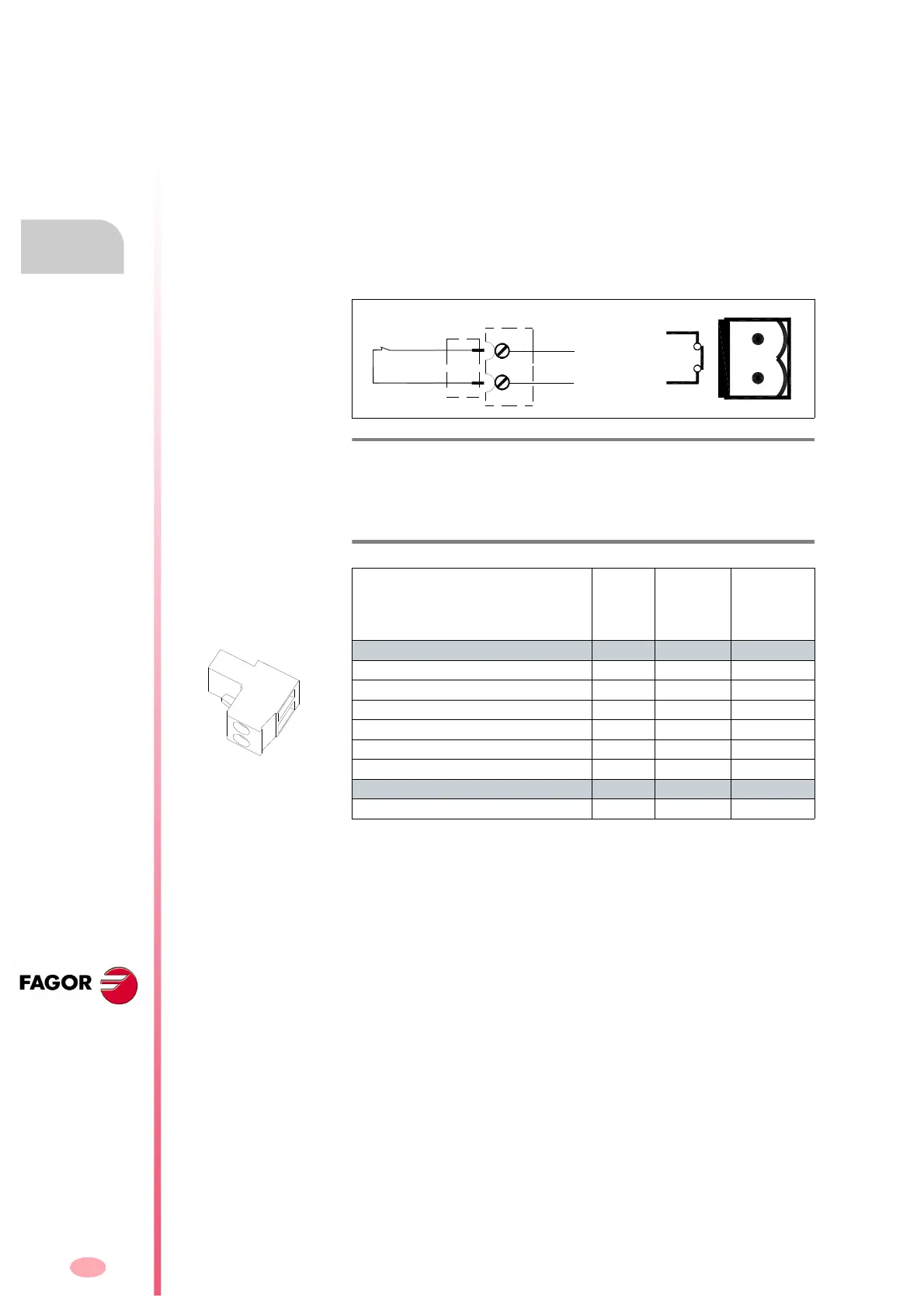
X7 connector
X7. Status of the integrated-safety relay
This connector X7 of the modular drive is associated with the second con-
tact (N.C., Normally Closed) of an internal safety relay (with guided con-
tacts). The status of the relay (initially closed) may be acknowledged
through the two pins and a CNC, PLC or control panel, i.e. that the inte-
grated safety relay has actually opened or closed. These two terminals
are identified at the drive as AS1-AS2. The opening or closing of this re-
lay depends on whether 24 V DC are present or not at pin 2 <DRIVE EN-
ABLE> of control connector X2. For further detail on this connector, see
section 9.2. Interface of chapter 9. FUNCTIONAL SAFETY in this manu-
al.
The following table shows the values for gap, tightening torque, sections
and other data of aerial plug-in connector X7:
F. H3/75
Connector X7. External acknowledgment of the status of the integrated
safety relay.
T. H3/12 Characteristics of the pins of connector X7.
AXD/SPD/MMC 1.08
1.15
1.25
1.35
2.50
2.75
2.85
3.100
3.150
3.200
3.250
Connector data
Nr of poles
22 2
Gap (mm) 5 5 5
Min/max tightening torque (Nm) 0.5/0.6 0.5/0.6 0.5/0.6
Screw thread M3 M3 M3
Min./max. section (mm²)
0.2/2.5 0.2/2.5 0.2/2.5
Rated current In (A) 12 12 12
Wire data
Length to strip (mm)
77 7