Drive modules
188
3.
DRIVE MODULES
Turning a drive on
186
DDS
HARDWARE
Ref.1310
3.3 Turning a drive on
When powering up the DDS module or doing a reset, various messages
appear on the seven - segment display:
1. Initialization stages: they show values of 1, 2, 3 and 4.
2. Software version, after the r with the identifying digits.
3. Error listing.
4. Warning listing.
5. Return to step 3.
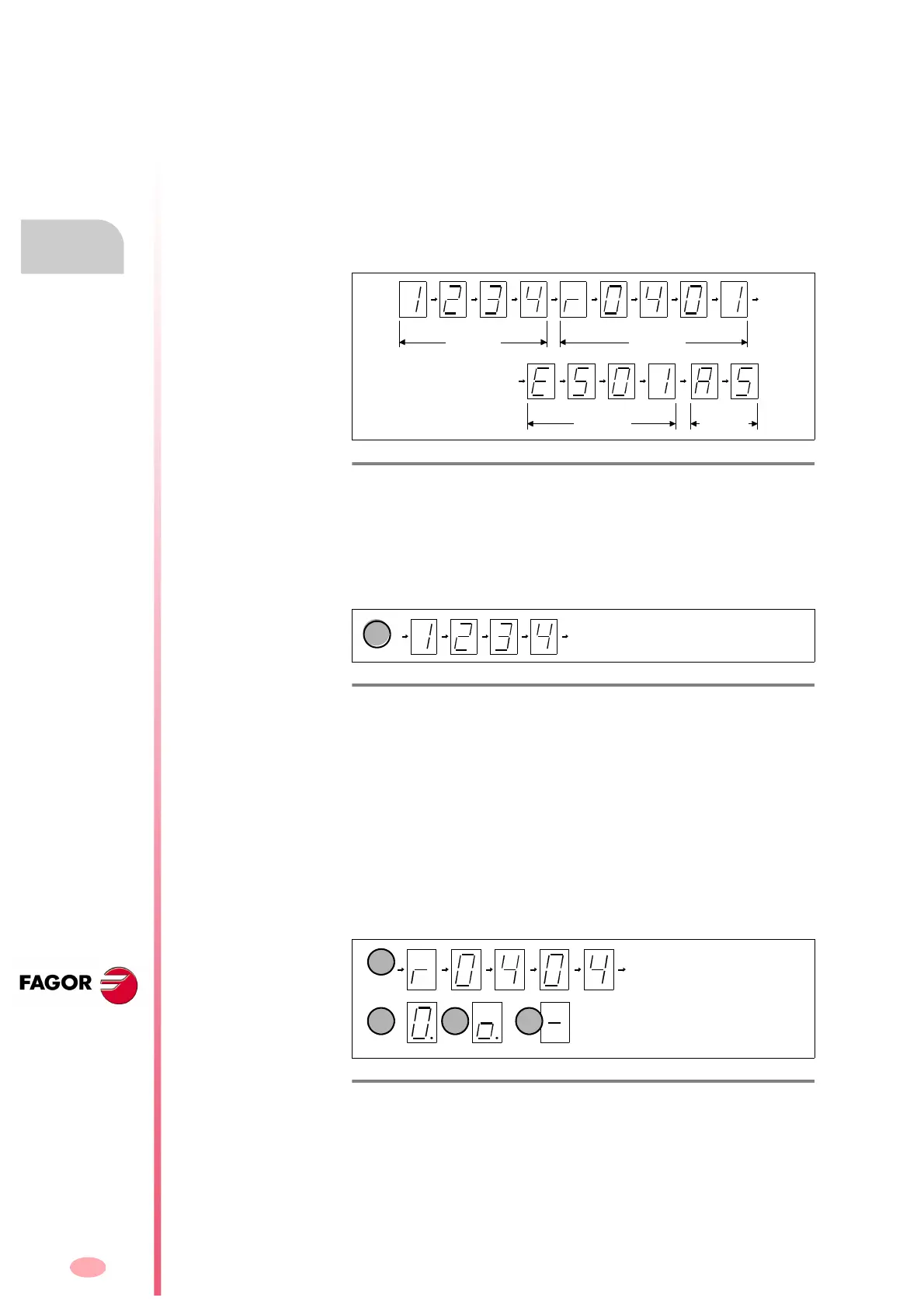
Stages shown on the 7-segment display:
Its purpose is to verify that the startup stages are being executed proper-
ly. The information sequences that it is showing in the start-up process
have the following meaning:
1. Initialization stage: After the display is turned off, digits 1, 2, 3 and 4
(a)
are shown which correspond to the 4 initialization stages. The display
then turns back off.
2. Software version displaying stage: It shows the software version load-
ed in the module. It first shows the letter r (indicating the version “re-
lease”), followed by the version number (digit by digit)
(b)
. When the
drive is active and the axis is being governed, the display will show
the zero digit with a blinking dot
(c)
.
While loading parameters, the display only shows the middle seg-
ment
(e)
.
When the drive (in a system with SERCOS interface) is not in stage 4,
i.e. the system communication between the CNC and the modules has
not finished initializing and although the light ring is closed, it has not
gone up to the next stage, the display shows a smaller fixed zero
(d)
(not blinking).
If this zero (smaller) is not fixed (blinks) it means that the light ring is
not closed (the light does not reach) or there is too much distortion.
This indication permits detecting which section of the optical fiber is
causing the problem (or which drive is not sending light).
Hence, the module whose display blinks this smaller zero is the one
that is not receiving light at the input.
F. H3/141
Module startup stages.
F. H3/142
Initialization stage. STAGE 1.
F. H3/143
Stage to display the software version and other indications
PHASE 2
PHASE 3
PHASE 1
PHASE 4