Cables
CABLES
Power cable. Motor-drive connection
7.
249
DDS
HARDWARE
Ref.1310
7.2 Power cable. Motor-drive connection
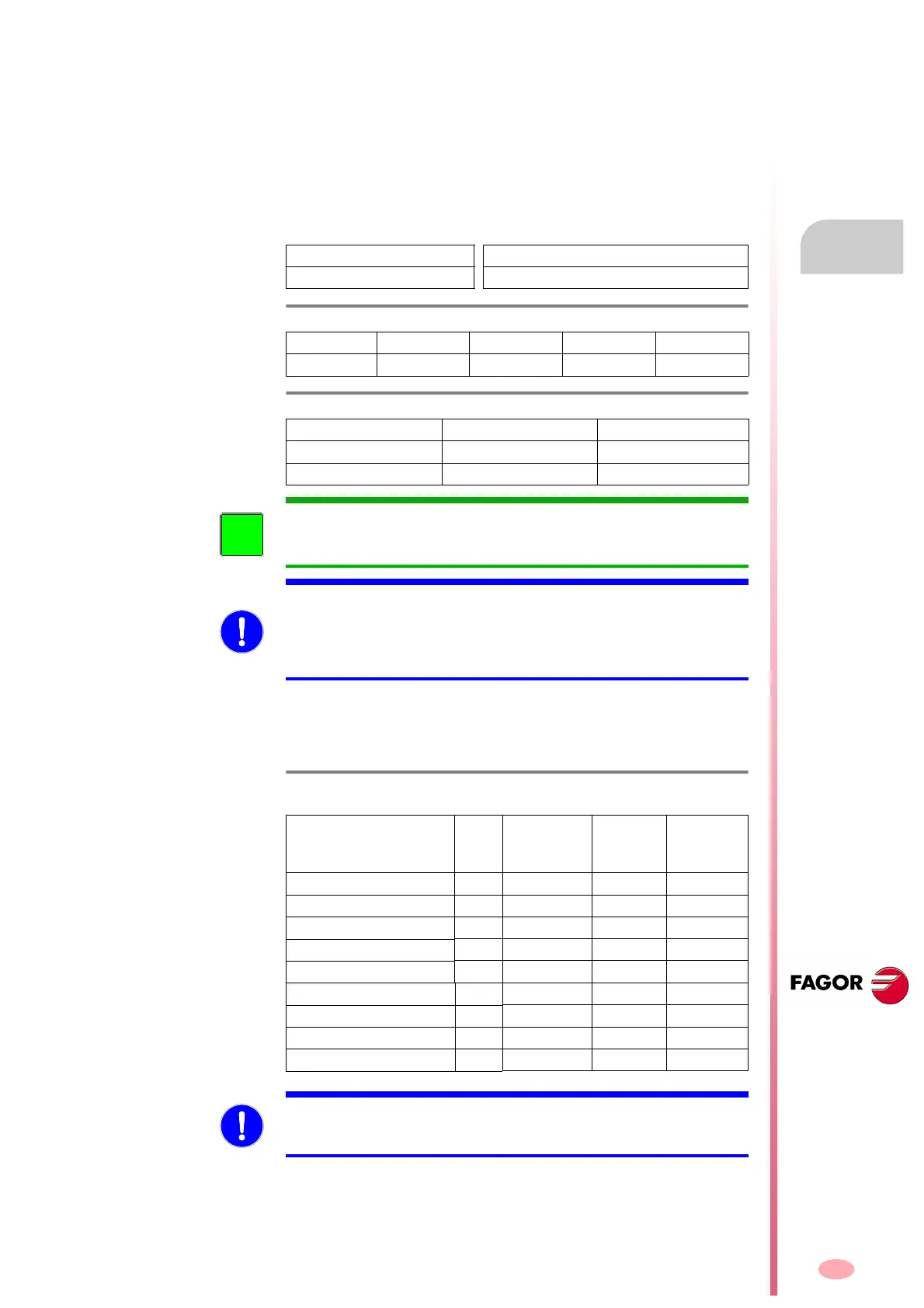
Table T. H7 /4 and table T. H 7/ 5 show the range of power cables supplied
by FAGOR to connect a motor and a drive.
They are supplied without
connectors
because the power connector will usually be different de-
pending on the motor it will be connected to. The number of meters avail-
able upon request. It is available in lengths of 5, 10, 15, 20, 30, 40, 50,
75, 100, 150, 200, 250 and 300 meters for sections up to 10 mm² (includ-
ed) and 5, 7, 10, 12, 15, 20, 25, 30, 35, 40, 45, 50, 75 and 100 for sec-
tions of up to 50 mm
2
(included). Their sales reference is:
Power terminals. Mechanical characteristics
The mechanical characteristics of the terminals (U, V, W, PE) on modular
drives are:
For further details on the connector that must be mounted at the end of
the MPC cable and connected at the motor end, see the manual of the
corresponding motor.
MPC-4
x
to connect motors without brake
MPC-4
x+(2x)
to connect motors with brake
T. H7/4 Range of cables to connect a motor (without brake) and a drive.
MPC-4x1.5 MPC-4x4 MPC-4x10 MPC-4x25 MPC-4x50
MPC-4x2.5 MPC-4x6 MPC-4x16 MPC-4x35 MPC-4x70
T. H7/5 Range of cables to connect a motor (with brake) and a drive.
MPC-4x1.5+(2x1) MPC-4x6+(2x1) MPC-4x25+(2x1)
MPC-4x2.5+(2x1) MPC-4x10+(2x1)
MPC-4x4+(2x1) MPC-4x16+(2x1.5)
INFORMATION. Remember that when a motor is mentioned here, it re-
fers to any motor of the FAGOR catalog, both synchronous and asynchro-
nous.
MANDATORY. In order for the system to comply with the European Di-
rective on Electromagnetic Compatibility, the cable hose that carries 6 or
4 cables, depending on whether the motor has a brake or not, must be
shielded and connected at both ends; i.e. both at the drive end and a the
motor end. This condition is a must.
T. H7/6 Mechanical characteristics of the power connectors of the modular
drives.
Module Gap
(mm)
Max. tight-
enin torque
(N·m)
Max. hole
section
(mm²)
Min. cable
section
(mm²)
AXD/SPD/MMC 1.08/1.15 7.62 0.6 4 2.5
AXD/SPD/MMC 1.25 7.62 0.8 6 6
AXD/SPD/MMC 1.35 10.16 1.5 6 6
AXD/SPD/MMC 2.
10.16 1.8 16 16
SPD 2.85 10.16 1.8 16 16
AXD/SPD/MMC 3.100 - 8 50 25
AXD/SPD/MMC 3.150 - 8 50 50
SPD 3.200 - 20 95 70
SPD 3.250 -
20 95 95
MANDATORY. The cable wires connected at the motor end must be kept
inside their corresponding connector. The connector will be different de-
pending on the user's motor.