Cables
CABLES
RS232/RS422 BE adapter
7.
259
DDS
HARDWARE
Ref.1310
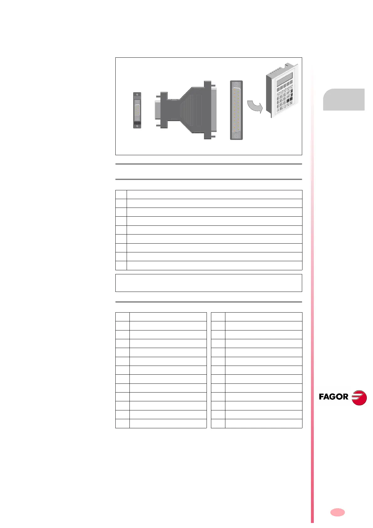
7.6 RS232/RS422 BE adapter
Before showing other connections, it shows the RS232/RS422 BE adapt-
er and the pinout for each end.
F. H7/7
RS232/RS422 BE adapter.
T. H7/24 Description of the pinout of port B connector.
1 N.C. (not connected)
2 T x RS232 OUT
3 R x RS232 IN
4 N.C. (not connected)
5 RS232 GND
6 R x RS422 + IN
7 R x RS422 - IN
8 T x RS422 + OUT
9 T x RS422 - OUT
NOTE. The pinout for port A is the same as for the MSP port of the VT
panel from ESA.
T. H7/25 Description of the pinout of port A connector.
1 N.C. (not connected) 14 IKT OUT
2T x RS232 OUT 15IKR OUT
3 R x RS232 IN 16 + 5 V DC (reserved)
4 RTS RS232 OUT 17 N.C. (not connected)
5 CTS RS232 IN 18
*R x C.L. + IN
6 N.C. (not connected) 19 N.C. (not connected)
7 GND 20 N.C. (not connected)
8 N.C. (not connected) 21 N.C. (not connected)
9
*T x C.L. + OUT 22 T x R x 485 + IN / OUT
10 T x R x 485 - IN / OUT 23 T x RS422 + OUT
11
*T x C.L. -OUT 24 R x RS422 - IN
12 T x RS422 - OUT 25
*R x C.L. - IN
13 R x RS422 + IN
* C. L. : Current loop.
Connect this end of
the adapter directly to
the MSP connector of
the VT
B port of the adapter
(Sub-D, M9)
Connect the end of the
RS-232 or RS-422 cable
to this end of the adapter.
RS422/RS232 BE
Adapter
A port of the adapter
(Sub-D, M25)
6
9
1
5
1
13
25
14