247
7
DDS
HARDWARE
Ref.1310
CABLES
This chapter describes the cables needed to install the DDS servo drive
system and the characteristics of the connectors of those cables. It also
describes the mechanical characteristics of those cables.
Previous chapters of this manual already described the cabling of the
DDS system for the power lines, feedback, optic fiber of the SERCOS ring
or CAN bus connection, RS-232/422 serial line connection, communica-
tions etc.
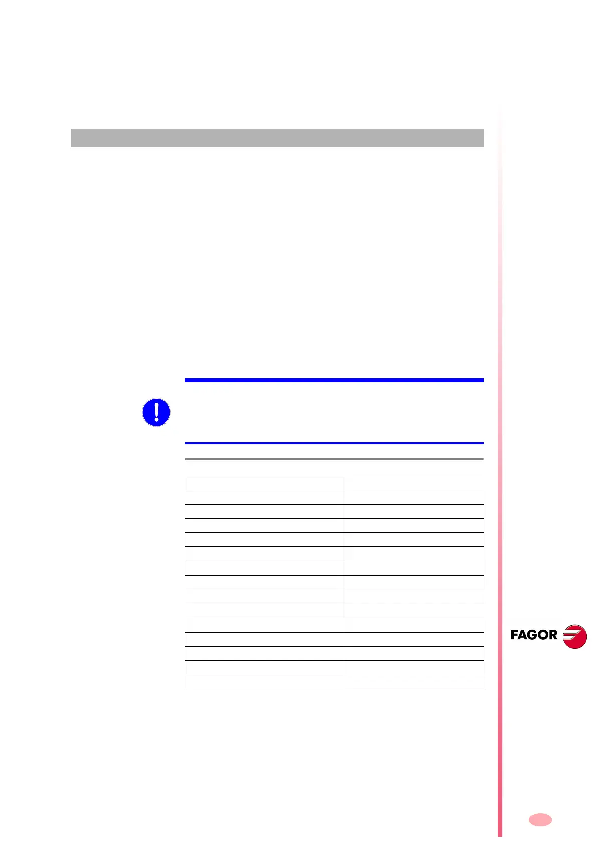
The attached table
T. H 7 / 1 gathers the regulation applicable to typical in-
stallation of drive systems.
It determines the minimum section of the cable through which the maximum
current allowed in continuous duty can circulate on three-phase wires in
PVC hoses or installed on the machine through conduits or channels ac-
cording to EN 60204-1.
The ambient temperature is assumed to be 40 °C (104 °F).
MANDATORY. The dielectric insulation of the cable must be enough to
withstand the test voltage at a minimum of 2000 V AC for 5 minutes for
cables supporting voltages over 50 V AC (alternating current) or 120 V
DC (direct current). Refer to the recommendations of the cable manufac-
turer before doing the installation.
T. H7/1 Cable section / Imax current.
Section (mm²) Imax (Arms)
0.75 8.5
1.0 10.1
1.5 13.1
2.5 17.4
423
630
10 40
16 54
25 70
35 86
50 103
70 130
95 156
120 179