25
1
DDS
HARDWARE
Ref.1310
DESCRIPTION
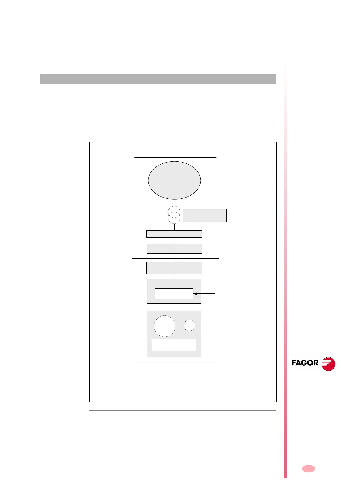
The DDS servo drive system is ready to be used in industrial environments. It
may be used with the CNC to control the movements and devices of the ma-
chine. The configuration of the main DDS servo drive system follows this gener-
al diagram:
Each element that make up the previous diagram will be explained in detail in the
following chapters.
F. H 1/ 1
DDS servo drive system description.
Mains
Power switch
MAINS FILTER A
(1
Motor
E/R
Motor with encoder
or resolver (position)
Transformer or
autotransformer
Main switch
Fuses (required)
Differential breaker
DDS
Power Supply
Power Module
Closed loop
control
(2
NOTE 1. The mains filter may be installed indistinctly before or after the
power contactor - KM1. NOTE 2. The position value may be sent either to
the drive or to the CNC to close the loop.