Drive modules
188
3.
DRIVE MODULES
Modular drives
144
DDS
HARDWARE
Ref.1310
Digital outputs
characteristics
Names of the PLC
resources
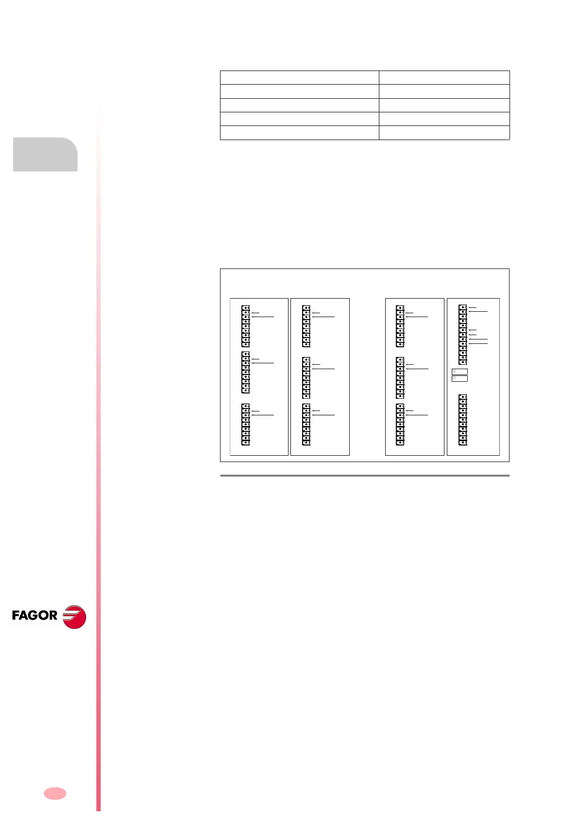
Inserting the cards in slots SL1 and SL2 permits all the possible combina-
tions except for two A1 type cards.
At the PLC, the input/output resources can be named according to their
location in SL1 and/or SL2:
The card inserted in slot SL1 numbers the pins from I1 and O1 on.
The card inserted in slot SL2 numbers the pins from I17 and O17 on.
The resources are numbered from top to bottom.
Maximum voltage 250 V
Maximum load current 150 mA
Current autosupply 200 mA
Maximum internal resistance 20
Galvanic isolation voltage 3750 V (1 min)
F. H3/82
PLC resources on cards located in SL1 and SL2.
8DI-16DO
1
13
1
11
1
9
A1
1
9
I3
I2
I1
1
9
1
9
1
9
I7
I6
I5
I4
O11
O10
O9
O8
O15
O14
O13
O12
O3
O2
O1
O7
O6
O5
O4
I3
I4
I1
I2
O4
O3
O2
O1
I19
I18
I17
16DI-8DO
1
9
1
9
1
9
I23
I22
I21
I20
I27
I26
I25
I24
I31
I30
I29
I28
O19
O18
O17
O23
O22
O21
O20
Drive Module (example)
I32
I8
O16O24
I19
I18
I17
I23
I22
I21
I20
I24
O27
O26
O25
O31
O30
O29
O28
O32
SL2 SL2SL1 SL1
Drive Module (example)
8DI-16DO
1
9
O19
O18
O17
O23
O22
O21
O20
O24
P2
P1
X8-DIG. INsX9-DIG. OUTsX10-DIG. OUTs
X13-DIG. OUTs
X12-DIG. INs X11-DIG. INs
X8-DIG. INs
X9-DIG. OUTsX10-DIG. OUTs
X6-DIGITAL I/OsX7-ANALOG I/Os