Drive modules
DRIVE MODULES
Compact drives
3.
165
DDS
HARDWARE
Ref.1310
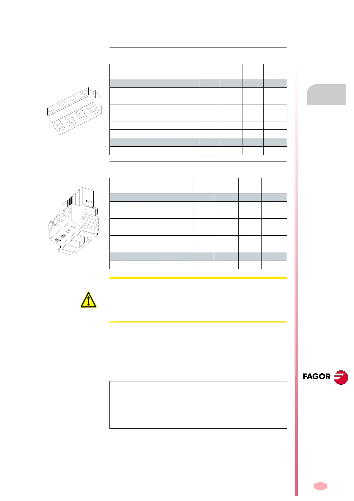
The following table shows the values for gap, tightening torque (wire en-
try holes) and other data regarding the screw-on terminals of the ballast
connectors according to drive model:
The terminals (Ri, Re and L+) are used to configure the Ballast circuit
whose purpose is to dissipate the energy generated while braking the mo-
tor.
By jumpering the terminals (Ri and L+), the system is configured so as to
work with the internal resistor of the compact drive module; this configura-
tion, as mentioned earlier, can only be set for ACD/SCD/CMC 1.08/1.15
models.
Up to 45 °C (113 °F), this resistor dissipates the power indicated in the
technical data table. See table
T. H3 /18 .
All the modules carry a protection against over-temperature which issues
an error E301 when reaching 105 °C (221 °F).
T. H3/20 Technical data of aerial connector for the external braking resis-
tor (Ballast) on ACD/SCD/CMC 1.15/1.25/2.35/2.50 drives.
ACD/SCD/CMC
1.08
1.15
1.25 2.35 2.50
Connector data
Nr of poles 4 4 4 4
Gap (mm) 7.62 7.62 7.62 7.62
Min/max tightening torque (Nm) 0.5/0.6 0.5/0.6 0.5/0.6 0.5/0.6
Screw thread M3 M3 M3 M3
Min./max. section (mm²) 0.2/2.5 0.2/2.5 0.2/2.5 0.2/2.5
Rated current In
(A) 12 12 12 12
Wire data
Length to strip (mm) 7 7 7 7
T. H3/21 Technical data of aerial connector for the external braking resis-
tor (Ballast) on SCD 2.75.
SCD 2.75
Connector data
Nr of poles 4
Gap (mm) 7.62
Min/max tightening torque (Nm)
0.7/0.8
Screw thread
M3
Min./max. section (mm²)
0.2/6
Rated current In
(A)
41
Wire data
Length to strip (mm) 10
WARNING. On ACD/SCD/CMC 1.08/1.15 modules, if an external Ballast
resistor (for braking) is going to be connected, make sure that its Ohm va-
lue is exactly the same as that of the internal Ballast resistor. See table
T.
H3/18
which indicates this value. The rest of the compact modules have
no internal Ballast resistor; therefore, always install the external Ballast
resistor supplied by FAGOR with the unit.
NOTE. Never configure models ACD/SCD/CMC 1.25/2.35/2.50 and SCD
2.75 with internal Ballast resistor (jumper between Ri and L+). These
modules do not have an internal Ballast resistor. If this warning is ignored
and a (L+, Ri) configuration is used instead of (L+, Re), either
unknowingly or inadvertently, there is no risk of destroying the module,
but the power bus will not charge.
Remember that pin Ri has no function
in these modules.