Installation
INSTALLATION
Connection between modules
8.
283
DDS
HARDWARE
Ref.1310
Connection to the external Ballast resistor
The external resistor modules are designed to be installed in the corre-
sponding terminals of the power supplies or compact drive modules (with
an integrated power supply) in order to dissipate the excess energy gener-
ated when braking the servomotors.
See chapter 5, the section regarding the “external Ballast resistor selection
guide” to know whether it is necessary or not to install an external Ballast
resistor or the internal one is enough.
See chapter 4, section
“RESISTOR MODULES”, for further detail on the
external Ballast resistors associated with the power supplies and with the
compact drives when required to install one.
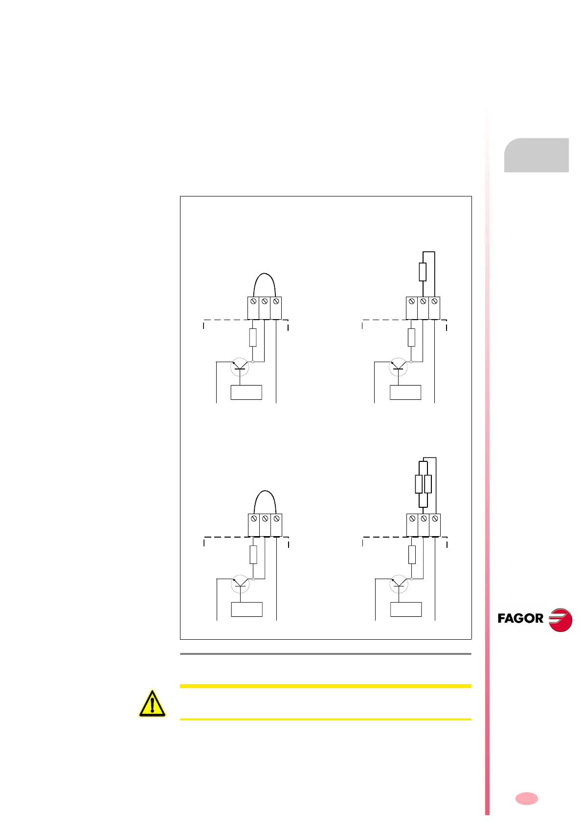
Resistor configurations with power supply
F. H8/12
Electrical configurations of the ballast resistor for power supplies.
C
ONTROL
L-
L+
R. int
R. ext
2x ER+TH-18/X
PS-65A
XPS-65
L+
Re
Ri
R. int
L+ReRi
C
ONTROL
2x ER+TH-18/X+FAN
PS-65A
XPS-65
L-
L+
Configuration
for connecting the
internal
Ballast resistor
Configuration
for connecting the
external
Ballast resistor
C
ONTROL
L-
L+
R. int
Configuration
for connecting the
internal
Ballast resistor
R. ext
ER+TH-18/X
PS-25B4
XPS-25
L+
Re
Ri
R. int
L+ReRi
C
ONTROL
ER+TH-18/X+FAN
PS-25B4
XPS-25
L-
L+
Configuration
for connecting the
external
Ballast resistor
WARNING. Never connect an external resistor in parallel with the internal
Ballast resistor. It may cause severe damage to the system.