EasyManuals Logo

Fagor DDS User Manual

Fagor DDS
386 pages
To Next Page IconTo Next Page
To Previous Page IconTo Previous Page
Page #294 background imageLoading...
Page #294 background image
Installation
312
8.
INSTALLATION
Connection of the control and communications signals
294
DDS
HARDWARE
Ref.1310
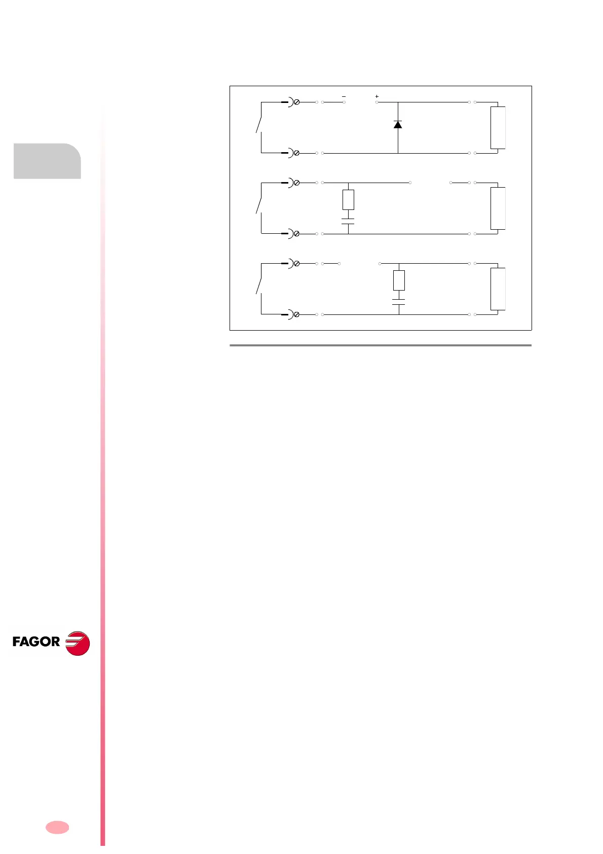
Connection for the digital outputs
When the drive outputs are connected to inductive loads, we must protect
the optocoupler with circuits such as the ones shown in the next figure:
F. H8/23
Protection circuits for the opto-coupler of the digital output with inductive
loads.
DC
AC/DC
1N4000
Vbr=2.4 V DC
IF=Load
(1
)
C
0.1-1mF 250V
R ~1
C
0.1-1mF 250V
LOAD LOAD LOAD
AC/DC
R ~1

Other manuals for Fagor DDS

Questions and Answers:

Question and Answer IconNeed help?

Do you have a question about the Fagor DDS and is the answer not in the manual?

Fagor DDS Specifications

General IconGeneral
BrandFagor
ModelDDS
CategoryServo Drives
LanguageEnglish

Related product manuals