Installation
312
8.
INSTALLATION
Connection of the control and communications signals
296
DDS
HARDWARE
Ref.1310
Interconnection
Connect in the SERCOS ring all the drives that will be governed by the
CNC.
With each fiber optic line, connect the OUT terminal of the first drive
with the IN terminal of the next adjacent drive.
Repeat this procedure with the second drive and so on up to the last
drive.
Connect the OUT terminal of the last drive with the IN terminal of the
CNC.
Connect the IN terminal of the first drive with the OUT terminal of the
CNC.
When all these connections have been made, the ring will be closed. See
figure
F. H8/24.
NOTE. With each drive, FAGOR supplies a fiber optic line to connect it to
its adjacent module and, upon request, the rest of the required optical fi-
ber. See chapter
7. CABLES.
F. H8/24
General connection diagram for the SERCOS ring between the CNC and
the drives.
NOTE. Note that if the machine has two separate servo drive system
(each with its own power supply) and a single CNC, the same ring must
interconnected all the drives of the machine.
C
D
E
F
0
B
A
9
8
1
7
2
6
3
5
4
IN
OUT
NODE
IN
OUT
C
D
E
F
0
B
A
9
8
1
7
2
6
3
5
4
NODE
IN
OUT
C
D
E
F
0
B
A
9
8
1
7
2
6
3
5
4
NODE
IN
OUT
C
D
E
F
0
B
A
9
8
1
7
2
6
3
5
4
NODE
C
D
E
F
0
B
A
9
8
1
7
2
6
3
5
4
CNC SPINDLE X AXIS Y AXIS
Node=2Node=1Node=3Node=0
C
D
E
F
0
B
A
9
8
1
7
2
6
3
5
4
C
D
E
F
0
B
A
9
8
1
7
2
6
3
5
4
C
D
E
F
0
B
A
9
8
1
7
2
6
3
5
4
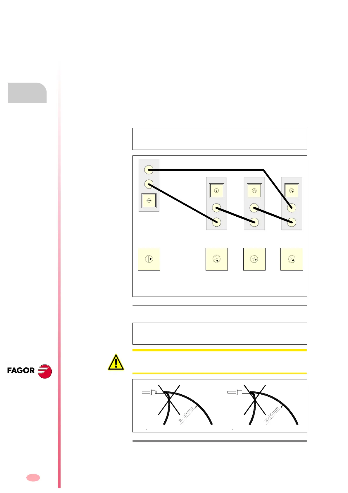
Note. Remember that for sections longer than 40 meters, you must use
the fiber optic cable (SF0-V-FLEX).
WARNING. The bending radius of fiber optic cables SF0 and SF0-FLEX
must always be more than 30 mm. For SF0-V-FLEX cables, this radius
must be more than 60 mm.
F. H8/25
Minimum bending radius. A. Fiber optic cables SF0 and SF0-FLEX. B. Fi-
ber optic cable SF0-V-FLEX.