10.
F. H1 0/3 0
DIGITAL INPUT
X1
X2
GND
I8
I1
N.C.
I2
I3
I4
I5
I6
I7
GND
I16
I9
N.C.
I10
I11
I12
I13
I14
I15
DIGITAL OUTPUT
X1
X2
GND
O8
O1
+24V
O2
O3
O4
O5
O6
O7
GND
O16
O9
+24V.
O10
O11
O12
O13
O14
O15
POWER SUPPLY
FAGOR
DRIVE
SPD
PS-65A + APS24 (X2, X3 & X4) 24 V DC, 10 A
PS-25B4 (X4, X5 & X6) 24 V DC, 10 A
XPS-XX (X4, X5 & X6) 24 V DC, 8 A
RPS-XX (X2) 24 V DC, 8 A
24 V (of the FAGOR power voltage)
0 V (of the FAGOR power voltage)
K3
K2
K1
K4
*
GND
CAN L
SHIELD
SHIELD
CAN H
X3
GND
CAN L
SHIELD
SHIELD
CAN H
X2
POWER SUPPLY
4
0
1
F
D
C
B
9
8
7
5
3
ADD MSB
LINE TERM
10
12
ADDRESS
RESET
POWER
SYSTEM READY
+5 ERROR
+5 OVER CURRENT
OVER VOLTA GE
+5V
X1
GND IN
CHASIS
GND IN
+24V IN
SYSTEM
READY
K1
K2
A1
A2
Auxiliary relays - KA3, - KA4. e.g. RP821024
Flywheel diodes D3, D4. e.g. 1N4934
24 V
24 V
0 V
OUTPUT 24 V DC
Chassis
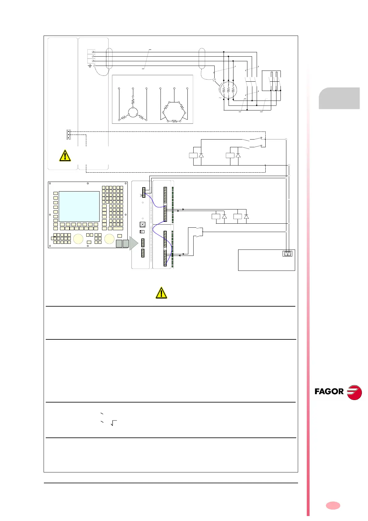
THE STAR/DELTA
SWITCH IS MANAGED
BY THE PLC PROGRAM
AT THE 8070 CNC
*
Flywheel diode
1N4934
24 V
0 V
0 V
24 V
A1
A2
0 V
I10
I11
REMOTE I/O
A1
Flywheel diode
1N4934
CANFagor
INTERFACE
0 V
24 V
O11
O10
A2
A1
A2
EXTERNAL AUXILIARY
POWER SUPPLY
- KM2
Star
- KM1
Delta
MPC- 4xN
2
U/U1
V/V1 W/W1
U
V
W
MCP- 4xN
1
MPC- 4xN
1
MPC- 4xN
1
MPC- 4xN
1
M
3
MPC- 4xN
1
X/U2
Y/V2 Z/W2
- KA1 D3 - KA2 D4
- KA4
D3
- KA3
D4
(*) WARNING. Never connect an external
auxiliary power supply and a Fagor power
supply at the same time.
Important warnings.
1. Either an external auxiliary power supply or a FAGOR power supply may be used to supply the 24 V DC. Never con-
nect both at the same time !
2. To brake the motor in a controlled way during a power failure, make sure that 24 V DC will be supplied to contactors -
KM1 and - KM2 and relays - KA3 and - KA4. This situation is ensured if you have installed a FAGOR power supply next
to an SPD modular drive. If you have installed an external auxiliary 24 V DC power supply, you must make sure that this
condition is ensured.
3. When using a compact SCD drive to govern a spindle motor, you must necessarily install an external auxiliary power
supply to provide the 24 V DC. These compact drives do not have an output 24 V DC connector
.
Note. See these currents in chapter 6. Selection, of the FM7/FM9 motor manual.
Sizing of motor power cables.
Note. See the necessary cable section according to table of the chapter 4. Installation of the FM7/FM9 motor manual.
If you decide to install an external auxiliary power supply, make
sure that in case of a power outage, the 24 V DC are ensured
to brake the motor under control preventing it from braking by
inertia. Ignoring this warning may cause personal injury.
Notes.
The I/O selected in the figure have been chosen arbitrarily. In general any Ixx and Oxx may be used always matching
the ones used in the PLC.
It is very common to choose I1 and O1 for the external emergency. Therefore, we suggest not to use them for this appli-
cation. If they are going to be used, make sure that they have not been set to be used as emergency input and output.
Sizing of - KM1 and - KM2 power contactors.