Power supplies
94
2.
POWER SUPPLIES
Regenerative power supplies
56
DDS
HARDWARE
Ref.1310
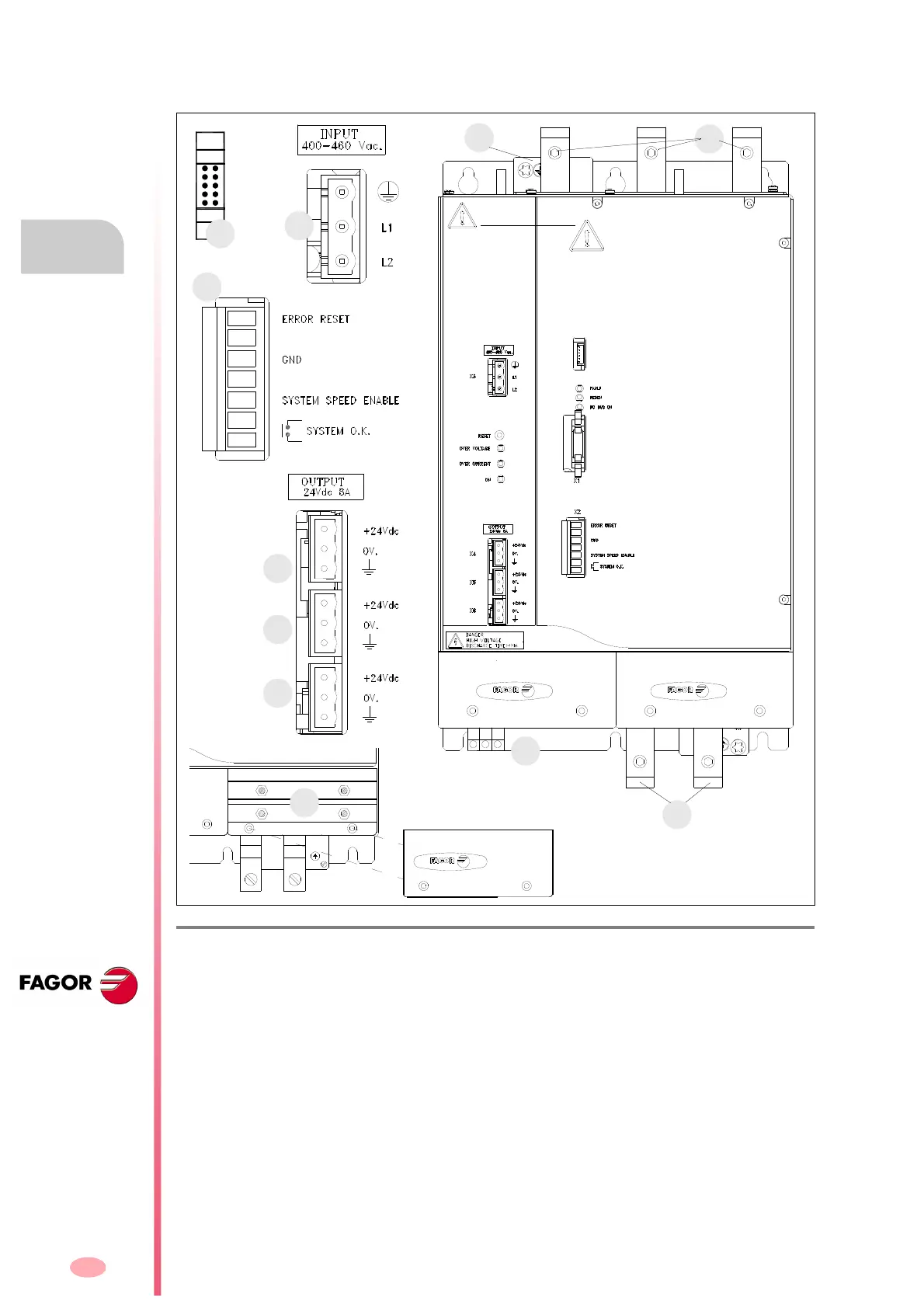
XPS-65. Connector description
The regenerative power supply XPS-65 has the following connectors:
F. H2/18
Connectors of the PS-65 power supply.
1. Power connector for the three-phase mains.
2. Power connector for the external Ballast resistor connection.
3. Ground connection for the mains cable.
4. Power Bus supplying power to the drive modules through metal bars.
5. Connectors for the choke of the XPS-65.
X1. Connector for inter-module communication.
X2. Connector for the basic control signals.
X3. Input connector supplying from mains to the auxiliary power supply integrated into the module. The
mains power is received through it. It admits a voltage between 400 and 460 V AC.
X4. Output connector of the auxiliary 24 V DC power supply integrated into the module.
X5. Output connector of the auxiliary 24 V DC power supply integrated into the module.
X6. Output connector of the auxiliary 24 V DC power supply integrated into the module.
Ri Re L+
CH1 CH2
L1 L2 L3
XPS 65
5.
1.
3.
X2.
X1.
X4.
X5.
X6.
X3.
4.
2.
CAUTION. AC touch current
greater 3.5 mA. Install ground wire
of at least 10 mm² Cu or 16 mm²
Al.