Power supplies
POWER SUPPLIES
Regenerative regulated power supplies
2.
81
DDS
HARDWARE
Ref.1310
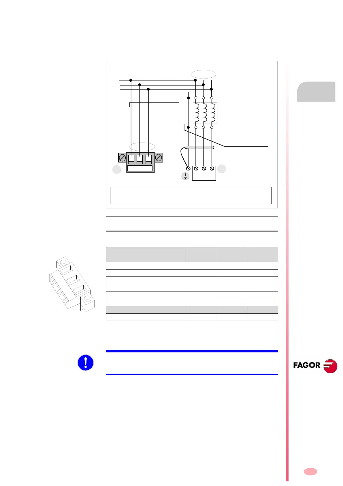
Terminal strip for connecting the mains voltage input
Three-phase line input taken at a point before the three single-phase RPS
chokes (one choke per phase). This connection is needed to receive the
mains line voltages and it is done through connector (2) as shown in the
next figure:
The max. current circulating through the wires (screwed into this connec-
tor) will be 8.5 mA for a mains voltage of 460 V AC (rms) Therefore, use
wires with a minimum section of 1 mm².
For further detail, see chapter 6. POWER LINE CONNECTION of this man-
ual.
Connection to an external braking resistor (Ballast)
RPS power supplies do not carry a Ballast circuit and, consequently,
FAGOR does not have external braking resistors (Ballast) associated with
them. In applications requiring a Ballast circuit, one off-the-shelf will have to
be installed.
F. H2/42
Terminal strip for connecting the mains voltage input.
T. H2/30 Data of the pins of the mains voltage sensor connector. See
connector 2 of the previous figure.
Connector data
RPS-80
RPS-75
RPS-45 RPS-20
Nr of poles 3 3 3
Gap (mm) 7.62 7.62 7.62
Min/max tightening torque (N·m) 0.5/0.6 0.5/0.6 0.5/0.6
Screw thread M3 M3 M3
Min./max. section (mm²) 0.2/2.5 0.2/2.5 0.2/2.5
Rated current In (A) 12 12 12
Wire data
Length to strip (mm) 7 7 7
L3L2L1
The RST phases may be
connected in any sequence
LINE VOLTAGE
INPUT CONNECTOR
L1 L2 L3
L3L2L1
From mains
ST R
N
L1 L2 L3
2
)
Cable without connectors
MPC - 4x ... (mm
2
)
POWER CONNECTOR
Choke RPS-XX
u1
v1
w1
w2
v2
u2
Important note: Make sure that if the phase sequence is e.g. S-L1,T-L2,R-L3
at the power connector, it must then match the sequence set at the line voltage
connector; that is: S - L1, T-L2, R-L3 .
RTS
MANDATORY. The phase order in the line voltage input (2) must be exactly
the same as the one selected at the power connector (1). See figure F.
H6/2.