40
(MT11 - Gb2012)
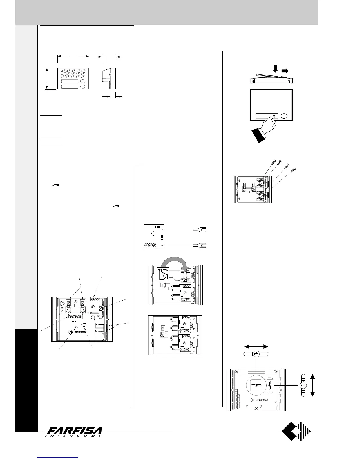
In any button module, in order to avoid the
dismounting of name holder, insert a 3MAx12
screw in the holes shown in the picture for each
name plate to be blocked. Screws are not sup-
plied by the manufacturer.
Dismounting of name holder to insert name
label.
Dismounting and protection of name la-
bels
A1S
PEP
ANTILOCALE
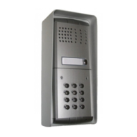
AMPLIFIED DOOR STATIONS
MD10ED. Module without call buttons, with
front plate in anodized aluminium, amplified
door speaker in two channels and control of
volume of "receiver".
MD11ED. Module with 1 call button.
MD12ED. Module with 2 call buttons..
Testing and adjustments
Adjustments are carried out in the factory; should
any be necessary they can be readjusted from
the outside with a screwdriver with the trimmers
identified by the words “antilocale” and “vol-
ume”(
).
Volume adjustment
To increase the volume from the amplifier in the
transmission mode, turn the trimmer “
” in a
clockwise direction.
Antilocale adjustment
In case of "feedback" (Larsen effect) in the
external unit it is necessary to operate as fol-
low:
- make the call from the door station and lift the
handset of an intercom;
- adjust the trimmer “antilocale” until the whis-
tling stops (Larsen effect).
4
5
6
7
1
2
4
3
1 Lamp terminals
2 Button terminal board
3 Call buttons common (terminal C)
4 Stair light button terminals
5 External volume adjustment
6 Feedback adjustment
7 Terminal board for audio/powering/electric lock
PEP
"
16
/
1
4
"
8
/
7
52
124
90
2
"
16
/
9
"
4
/
3
19
3
Adjustments
If necessary, you can manually modify the cam-
era position by means of the horizontal and
vertical adjustments located on the back of the
camera.
To do this, you must:
- remove the upper screw of the push-button
panel to access the back of the camera;
- loosen the screw of the horizontal or vertical
adjustment (or both screws, if you want to
adjust the image in all the directions);
- move the camera in the desired direction;
- tighten the screw to block the camera in the
desired position;
- fix the push-button panel.
Horizontal (± 15°)
Vertical (± 15°)
Terminals
A Supply 13VAC-70mA
- Ground
1 Reception-transmission; electric lock
release; call
S Electric lock
E Reception-transmission; electric lock release
P Call button
241D. Module with diodes for 2 users.
It allows for the use of the button modules
MD21, MD22, MD23, MD24, MD222, MD224,
MD226, MD228 in the 1+1 intercom systems
and 4+1 video intercom systems.
It is applied inside the button modules.
EXTERNAL DOOR STATIONS
1+1
INTERCOMS *
4+1
VIDEOINTERCOMS
M
O
D
Y