70
(MT11 - Gb2012)
1+1
INTERCOMS *
4+1
VIDEOINTERCOMS
Si 41MR/28
MULTI-WAY VIDEOINTERCOM SYSTEM CONNECTED TO ONE EXTERNAL DOOR STATION WITH SURVEIL-
LANCE CAMERA
EXTERNAL DOOR STATIONS
AGORA' series PROFILO series MATRIX series MODY series
1 AG100A ... PL71÷PL73 ... MA71÷MA73 ... MD71÷MD74
... AG100T 1 PL81÷PL89 ... MAS61÷MAS63 (
1
)1MD81÷MD812
... AG20 1 PL91÷PL99 * 1 MA91÷MA93 * 1 MD91÷MD912 *
... AG21 1 PL10PED÷PL12PED 1 MAS10PED÷MAS12PED 1 MD10ED÷MD12ED
... AG222 ... PL21÷PL228 ... MAS22, MAS24 ... MD21÷MD228
1 AG30ED ... PL20, PL50 ... MAS20 ... MD20, MD50
... 241DMA ... 241DMA ... 241D
INTERNAL STATIONS
ECHOS series EXHITO series COMPACT series
... EH9161CT ... EX3100C ... KM8111CW
... EH9161CW ... EX3160C ... KM8111W
... 9083 ... EX3160 ... WB8111
... WA9100T-W ... WB3161
... TA9160 ... TA3160
VARIOUS ARTICLES
1 1181E Timed power-supply
... DV2D-DV4D Video distributors
1 CV01 Video signal converter
1 TVT.. CCTV camera
1 H.. Lens with or without autoiris
1 CU.. Outdoor heated housing
1 AST.. Bracket for camera or housing
1 APS.. Power supply for camera
1 PA ** Door release push-button (optional)
1 SE ** Electric door lock (12VAC-1A)
... Refers to number of users.
(
1
) Or MA61÷MA63.
* Rain shelters are used instead of back boxes and hood covers.
** Articles not supplied by ACI Farfisa.
Working instructions. See page 52.
Notes
- For audio compatibility we do not suggest to connect door stations MODY series with internal devices ECHOS series.
- For the connection of name-plate lamps, read notes 6, 7 and 8 of the installation instructions on page 50.
- For wires dimensioning and video connection refer to the installation instructions and table on pages 50 and 51.
Agorà door station
Note. Door station AG100A do not have the terminal "E" because the requested
connection is automatically done inserting the pre-assembled cable which comes
with the product (see drawing 5a on page 18). On the contrary, do not forget to make
the connection between the terminal "1" of art. AG100A and terminal "E" of the
additional door stations AG100T’s (if any).
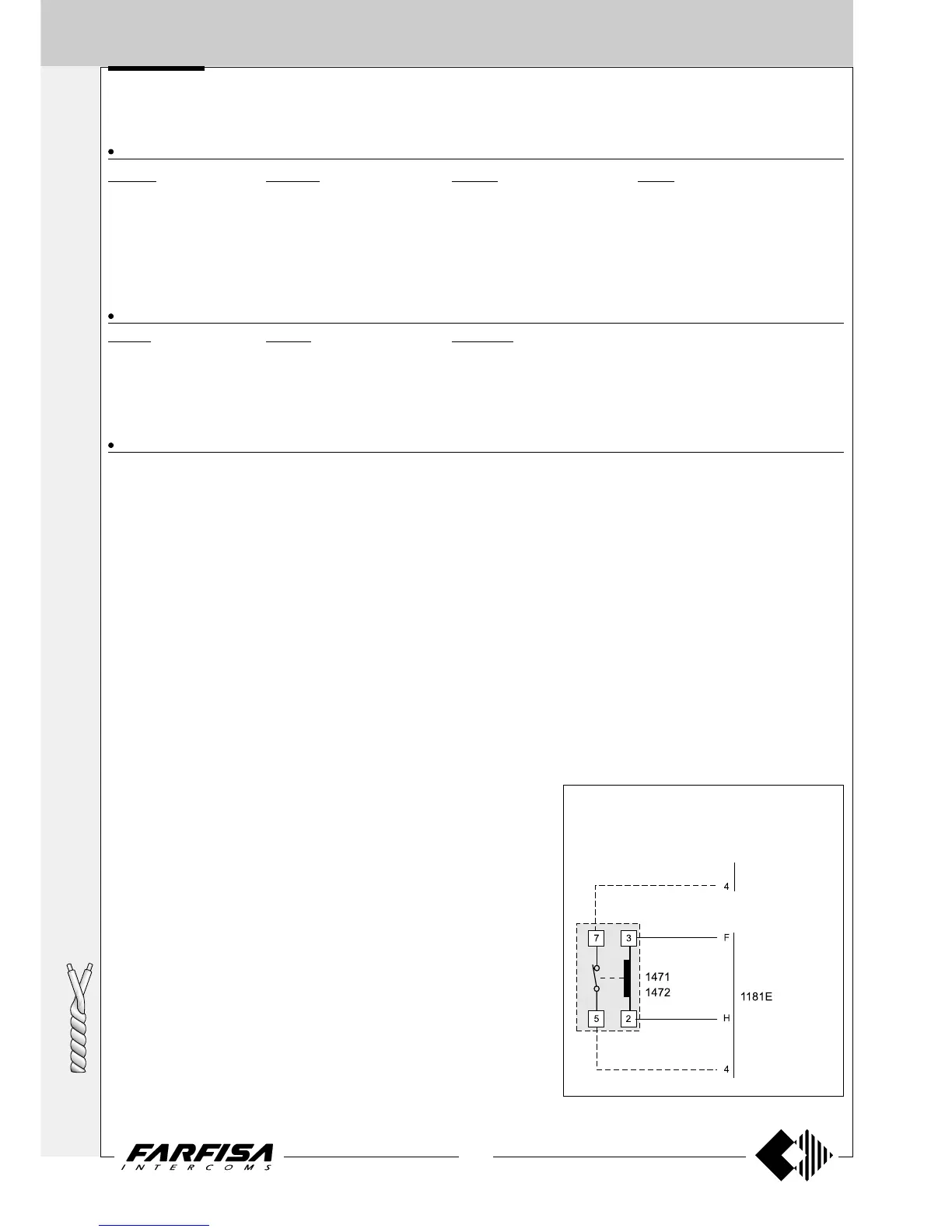
Control switching ON deactivation
To activate the control switching ON from the
videointercoms only when the system is in standby,
it is necessary to install a relay (type 1471 or 1472)
and connect it as shown on the diagram.
to the videoin-
tercoms