84
(MT11 - Gb2012)
1+1
INTERCOMS *
4+1
VIDEOINTERCOMS
Si 47MR/1
MULTI-WAY VIDEOINTERCOM SYSTEM WITH SECONDARY VIDEO STATIONS AND 2 MAIN COMMON VIDEO
STATIONS (multiple entrance)
EXTERNAL DOOR STATIONS
AGORA' series PROFILO series MATRIX series MODY series
2+X AG100V ... PL71÷PL73 ... MA71÷MA73 ... MD72÷MD74
... AG100T 2+X PL81÷PL89 ... MAS61÷MAS63 (
1
) 2+X MD82÷MD812
... AG20 2+X PL91÷PL99 * 2+X MA91÷MA93 * 2+X MD92÷MD912 *
... AG21 2+X PL40PCED÷PL42PCED 2+X MAS43CED 2+X MD10ED÷MD12ED
... AG222 PL40PED÷PL42PED MAS43ED 2+X MD41D
2+X AG40CED ... PL21÷PL228 ... MAS22, MAS24 ... MD21÷MD228
... PL20, PL50 ... MAS20 ... MD20, MD50
... 241DMA ... 241DMA ... 241D
INTERNAL STATIONS
ECHOS series EXHITO series COMPACT series
... EH9161CT ... EX3100C ... KM8111CW
... EH9161CW ... EX3160C ... KM8111W
... 9083 ... EX3160 ... WB8111
... WA9100T-W ... WB3161
... TA9160 ... TA3160
VARIOUS ARTICLES
2xX 1473 Exchanger
1+X 1181E Timed power-supply
1 PRS210 Transformer
2+... DV2D-DV4D Video distributors
2+X PA ** Door release push-button (optional)
2+X SE ** Electric door lock (12VAC-1A)
... Refers to number of users.
X Refers to number of stairways.
(
1
) Or MA61÷MA63.
* Rain shelters are used instead of back boxes and hood covers.
** Articles not supplied by ACI Farfisa.
Notes
- For audio compatibility we do not suggest to connect door stations
MODY series with internal devices ECHOS series.
- For the connection of name-plate lamps, read notes 6, 7 and 8 of the
installation instructions on page 50.
- For wires dimensioning and video connection refer to the installation
instructions and table on pages 50 and 51.
- With Echos videointercoms series it is possible to monitor also the
main entrances by connecting the terminals P1 and P2 of the Echos
videointercoms respectively to the terminals “6” and “3” of the
exchanger art. 1473 (DS2) connected to its own riser and by moving
the jumper J2 on the back of the videointercoms to the position 2-3
(see on page 4).
Working instructions.
As the basic system described on page 52, with the following variations:
- The audio-video functions and door lock opening are automatically
switched to the door station which has made the call and remain in this
state until a call from another entrance is received.
- Services to secondary door stations are independent and can be
operated at the same time.
Agorà door stations
Attention. In the door station AG100V of the
secondary entrances create the terminal "E"
cutting the red wire which connects the door
speaker AG40CED to the backlighting board
(see figure), than connect it to the terminals
"E" of additional AG100T’s (if any).
In the door station AG100V of the main
entrances only cut and insulate the conductor
“E” (red wire).
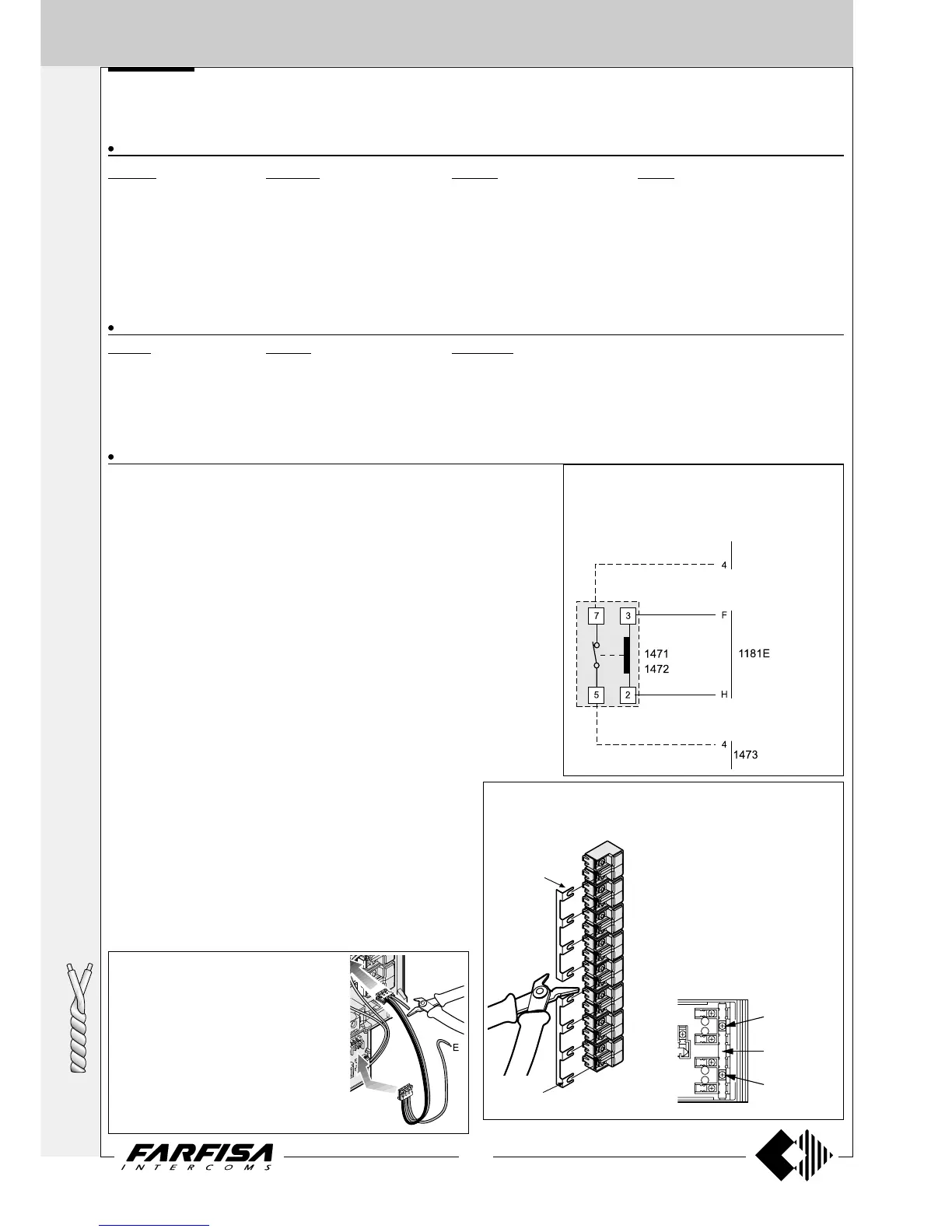
Control switching ON deactivation
To activate the control switching ON from the
videointercoms only when the system is in stand-by,
it is necessary to install a relay (type 1471 or 1472)
and connect it as shown on the diagram.
to the videoin-
tercoms
(DS1)
The main entrance push-button panel must have separate common
terminals. One common terminal for each secondary door station. The
common terminals of push-buttons Profilo and Matrix series can be
separated only module by module.
The common terminals of push-button
Agorà series can be separated according
to the requirements, by cutting
opportunely the common rail or just do
not using it.
Common buttons
building “a”
Common buttons
building “b”
Common of
button 1 and 2
To separate
common of
buttons cut here
Common of
button 3 and 4
In Mody series the common terminals
of push-buttons can be separated
module by module or every 2 push-
buttons by cutting opportunely the
common rail which connects the
common terminals of push-buttons.