ALYA INSTALLATION AND USER’S MANUAL - EN
Edition 2.0 Sept 2018 Pag. 17 di 32
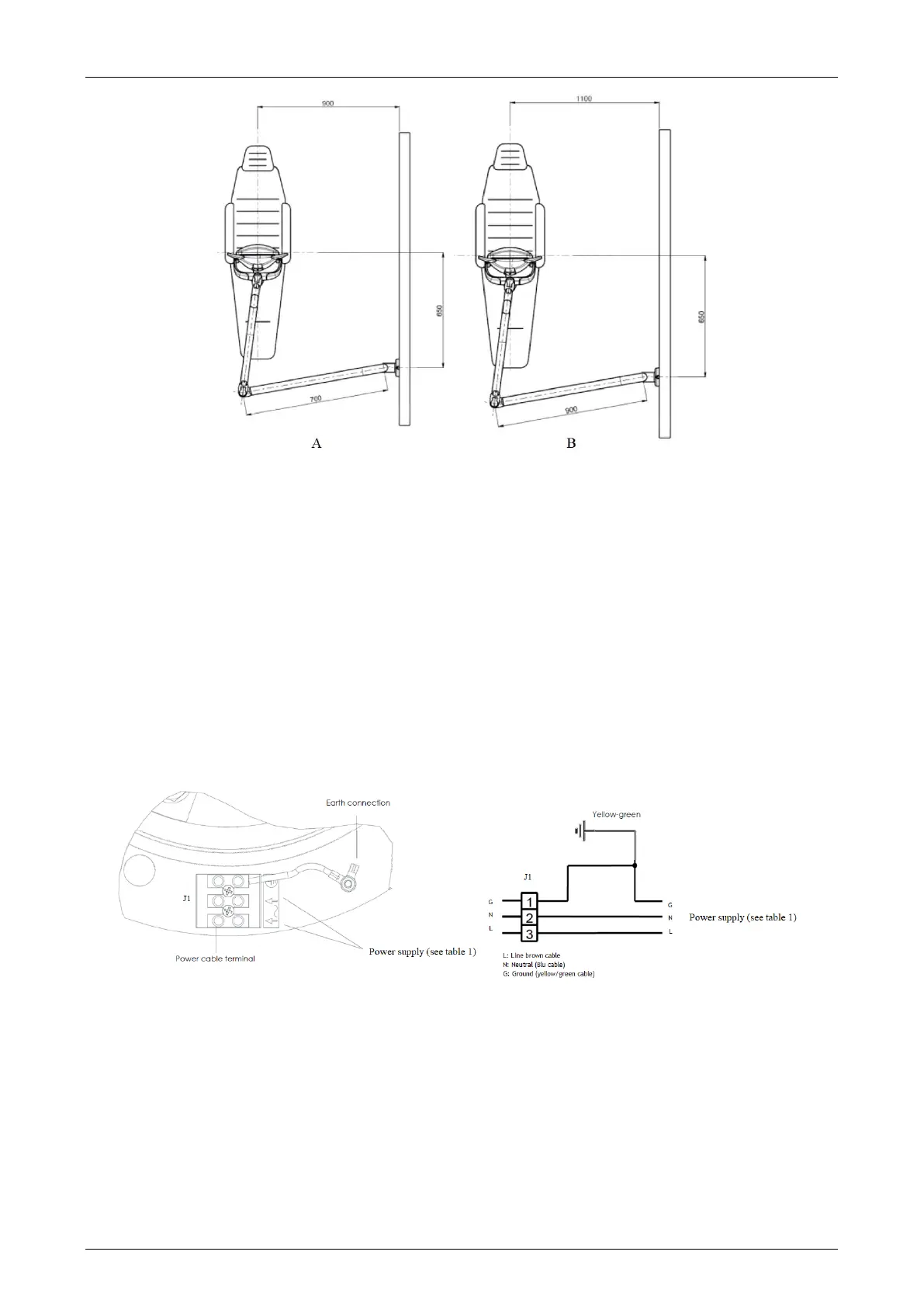
A. Once the fastening point has been established with reference to the center of the chair (See fig.A-B),
make three holes on the wall of diameter D 14 in correspondence with the holes in the wall
application (3), paying attention to the perpendicularity between hole and wall.
B. Insert the three wall plugs (12) into the holes made in A the screws (2) with the special hexagonal key
(support accessories), taking care not to crush the wire between the wall application (3) and the wall
itself.
C. Apply the three Caps (4) to the holes in the wall application (3).
D. Unscrew the screw (8). Remove the cover (7), insert the lamp in the ceiling application by greasing
the pin.
E. Connect the lamp wires to the terminal Electrical connector (5) (see wiring diagram below) including
the grounding wire.
F. Connect the wires coming out of the wall to the terminal board, in the
case had been previously walled up. In the absence of this precaution, the connection
it must be carried out with an external flying cable, to be introduced into the cable gland (10).
G. Mount the cover (7) using the screws (8).
3.2.7.1 Electrical drawing – wall mounting without transformer