ALYA INSTALLATION AND USER’S MANUAL - EN
Edition 2.0 Sept 2018 Pag. 9 di 32
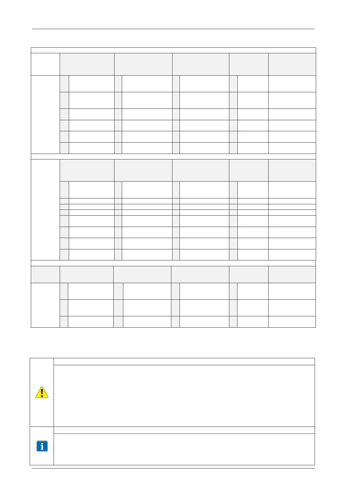
The identification of the variant of Alya supplied is managed through the speaking Part Number used.
The part number is made of 9 digits. In the table below is explained the meaning of the digits.
3 digit
Mounting e unit
control
4 digit
Supply voltage and
control interface
5 digit
rear arm lenght (mm)
x spring arm lenght
(mm)
7 8 9 digit
Customization
Joystick
17-24 Vac
50/60Hz
Proximity
17-24 V ac
50/60Hz
Joystick
230 V ac 50/60Hz
Proximity
230 V ac 50/60Hz
Joystick
240 V ac 50/60Hz
Proximity
240 V ac 50/60Hz
ALYA – Dental Light with Theia Tech option
3 Digit
Mounting+arm
lenght
(mm) (rear x spring)
5 Digit command
interface
Joystick auto-on +
remote cable
Proximity + remote
cable + auto on
3 digit
Col Temperature e
controllo riunito
4 digit –
Power supply and
control
Joystick
17-24 V AC
22-33 V DC
Optical Group
5000 K
On/Off
Proximity
17-24 V AC
22-33 V DC
(**) Customized codes include only aesthetic customization having no impact on Safety and EMC
requirements
3 DEVICE INSTALLATION
Warnings for electrical danger
The device must be installed by specialist technicians.
On installation, the power supply must always be disconnected.
Refer to the wiring diagrams in the manual.
Check the mainplate data before installation
The dental light must be installed on a specific control and power supply device, such as dental
units, or with an electrical system that meets standard IEC 60364-1 and “national installation
regulations for electrical systems in premises for medical use”.
When installed with ceiling, floor or wall applications the device must be installed with an
omnipolar separation device from the mains and compliant with Standard IEC 61058-1. This
separation device must be approved to withstand 4 kV of transient voltage.
The power supply cable on the complete light is supplied without any connector or terminal to
allow connection according to the specifications of the combination or application.
The functionality and safety of the light does not depend on the polarity of the power supply
current. Therefore inversion of the power supply cables will not pose a risk of malfunctioning.