13.3
.2 Crane with hydraulic tiltable supports (WITH CHAIN)
for outrigger rams:
(!) ATTENTION (!)
Be very careful during vehicle stabilization operation; make sure that there are
no obstacles preventing the rotation of the rams and that no one is or transits in
close proximity of the working area of the outriggers.
- Disengage the locking devices of the outrigger supports by putting the
levers A from the position of the fig. 6 to the one of the fig. 6a.
- Position lever D of oil diverter ( -E/S) on E/S.
- Position selector ( -E/S) of the push-button panel on E/S.
- By using the levers CD, the lever C and the valve taps, extend the outrigger
supports, rotate the outrigger rams putting in a working condition and lower
them till the complete stabilisation of the vehicle.
Example of using the levers CD, the lever C and the valve tap on the outrigger and the
valve tap on the control ram for the tiltable support:
- extension of the outrigger support n°1
- activate the lever CD n°1 in the direction of E;
- by keeping activated the lever CD n°1, activate the lever C in the opposite
direction.
- rotation of the outrigger ram n°1 from the rest position (fig. 7) to the working
condition (fig. 9)
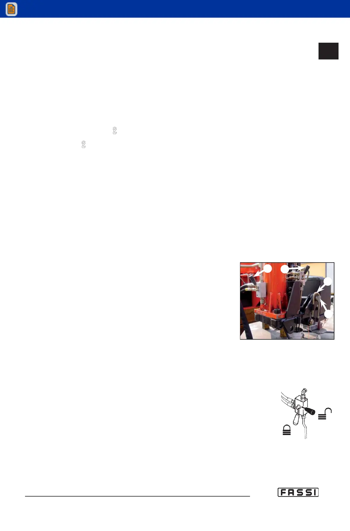
- make sure that the tap R1 of the valve of the outrigger ram S1 is closed
(for the closed or opened position see fig. 8);
- open the tap R2 of the valve of the control ram for the tiltable support;
- to remove the pin 2 proceed as follows:
- activate the lever CD n°1 in the direction of S;
- by keeping activated the lever CD n°1, activate the lever C in the oppo-
site direction to control the rotation and take the ram S1 to its rest posi-
tion so that the pin 2 is extractable;
- lift the parking pin 1 (safety) until it is released and remove from its seat the
pin 2;
- to rotate the outrigger ram S1 proceed as follows:
- activate the lever CD n°1 in the direction of S;
- by keeping activated the lever CD n°1, activate the lever C in the oppo-
site direction till the requested extension of the outrigger ram S1.
(!) ATTENTION (!)
Make sure that no one is or transits in close proximity of the working area of the
outriggers.
- manually complete the rotation by positioning the ram vertically, insert the
pin 2 in its new seat and lock it with the parking pin 1 (safety);
- close the tap R2 of the valve of the control ram for the tiltable support
(!) ATTENTION (!)
The locking pin 2 is constructed from special material. Do not replace it with
a non original part: your security depends on it
- descent of the outrigger ram n°1
- open the tap R1 of the valve of the outrigger ram S1;
- activate the lever CD n°1 in the direction of S;
- by keeping activated the lever CD n°1 activate the lever C in the opposite
direction till the requested extension of the outrigger ram S1;
- close the tap R1 of the valve of the outrigger ram S1.
13.3.2
SUPPLEMENTARY
BEAMS
GR5
R1
R2
2
1
fig. 7
fig. 8