16.8.1 Emergency control station on the column and
exclusion tap lever
(!) ATTENTION (!)
The distributor placed on the column (fig. 5) is to be used exclusively as
emergency control and only if its accessibility has been explicitly con-
templated by the crane configuration. In such condition in fact the only
admitted manoeuvre is the descent of the load on the ground; it is not
allowed to rotate the column in order to avoid all those situations which
may result in crushing or shearing against obstructions around the colu-
mn (tank, edge of the truck chassis, heat exchanger…).
When operating the emergency control using this distributor, consider
with extreme care the several elements in movement such as the crane
arms and rams in order to avoid the shearing of the operator.
If during the emergency, the distributor is not accessible due to the
above mentioned obstructions around the column, or it is not possible
to operate the emergency controls because the hydraulic circuit is faulty
(breakdown of one ram feeding pipe) or the oil is lacking in the distribu-
tor circuit (truck motor is off, the pump is faulty,…), call the assistance.
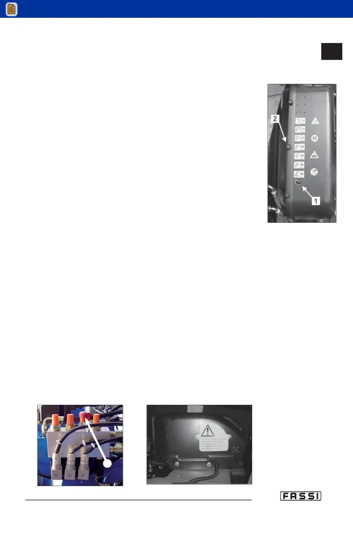
Operate the manual/radio switch with automatic release (fig. 5 pos.1) that
electrically restores the oil flow from the pump to the distributor (if accessible)
in the event of a failure of the remote control, as a temporary emergency mea-
sure, instead of removing the seals from the exclusion tap lever for the lifting
moment limiting device (drastic measure to be used only as the final option).
As compared to the exclusion device, such selector allows to keep the limiting
device active and therefore when the emergency is over, it is not necessary to
go to a Fassi authorized centre to reseal the exclusion tap lever.
This switch with automatic release enables also the reduction of the max
pressure in the feeding circuit at 200 bar and therefore it allows to stop the oil
feeding to the distributor in case of immediate danger, by simply releasing the
rotation switch.
In order to use the distributor in manual mode, remove the carter indicated in
fig. 5 pos. 2 and mount the appropriate levers.
In the event of a black-out or failure of the electronic limiting device, it has been
installed an emergency exclusion tap lever R (fig. 6) that, if activated, overrides
all crane emergency devices. Only in the event the crane cannot be manoeu-
vred otherwise, remove the original lead seal placed on the tap lever in order
to lower down the load on the ground, using the levers of the emergency distri-
butor mounted on the column.
When operating the tap lever, the working pressure of the crane is reduced.
For the access to the tap lever remove the yellow aluminium plate (fig. 7)
placed under the protection guard of the distributor by unscrewing the fixing
screws (10 mm hexagonal spanner).
16.8.1
CONTROLS TO OPERATE
THE CRANE
GR4_5_240B»1500AXP
- EVOLUTION
fig. 5
fig. 6
fig. 7
R