EasyManuals Logo
Home>Fastech>Controller>Ezi-Servo Plus R

Fastech Ezi-Servo Plus R User Manual

Fastech Ezi-Servo Plus R
104 pages
To Next Page IconTo Next Page
To Previous Page IconTo Previous Page
Page #53 background imageLoading...
Page #53 background image
www.fastech.co.kr
53
10. Control I/O Signal
10.3Connection Circuit
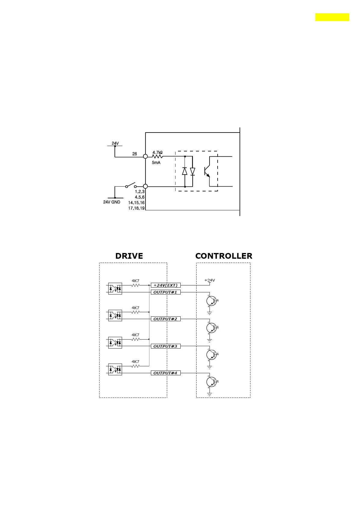
All drive I/O signals are insulated by a photocoupler. The signals display the internal
photocoupler status - [ON: Conduction] and [OFF: Non- Conduction], not the signal voltage
level.
1) Input Circuit
Input circuit power of DC24V±10% (consumed current : about 5mA/circuit) should be
separately prepared.
Connect NPN type Input signal
Connect the +24V externalsignal of drive to +24V of Controller .

Table of Contents

Questions and Answers:

Question and Answer IconNeed help?

Do you have a question about the Fastech Ezi-Servo Plus R and is the answer not in the manual?

Fastech Ezi-Servo Plus R Specifications

General IconGeneral
BrandFastech
ModelEzi-Servo Plus R
CategoryController
LanguageEnglish

Related product manuals