www.fastech.co.kr
10.5 Output Signal
1) ‘Compare Out’/ ’Trigger Pulse Output’Output
‘Trigger Pulse Output’ signal is displayed when specific conditions are performed. It
is fixed to CN1 connector’s COMP (Compare Out) pin. And it is available when the motor
needs to be synchronously controlled by an external controller. Refer to 「12.5 Trigger
Pulse Output」.
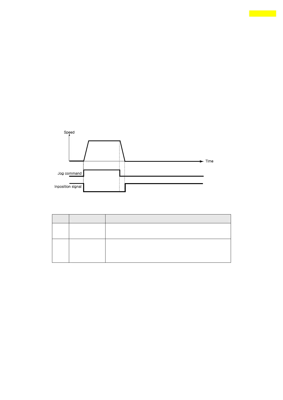
2) ‘Inposition’Output
After the motor stop in target position exactly on Servo ON status, the signal
becomes [ON]. The condition of this signal depends on parameter ‘Position Loop
Gain’and ‘Inpos Value’.
* Time delay of Output signal depends on the parameter‘Inpos Value’:
3) ‘Alarm’ & ‘AlarmBlink’Output
When the motor operates normally, alarm output becomes OFF. When the protective function
operates, alarm output becomes ON. The upper controller being used by the user detects
this alarm and then stops motor operation command. If overload or overcurrent occurs
while the motor is operating, the drive detects it and cuts off the motor’s current.
And alarm output is set to ON and also ‘AlarmBlink’ flash so that the user can check
abnormality type. The following table shows alarm type according to LED flash count.
Output the signal in 1[msec] after the motor stop
in target position.
Output the signal in maximum 100[msec] after the
motor stop in target position.
(Time is needed to check find exact positioning)
 Loading...