www.fastech.co.kr
12. Other Operation Functions
12.6 Push Motion
This function is used when the specified motor torque is needed during motioning and
Stop(only in Stop-mode) status.
This function is working only in absolute position value.
(1) Function
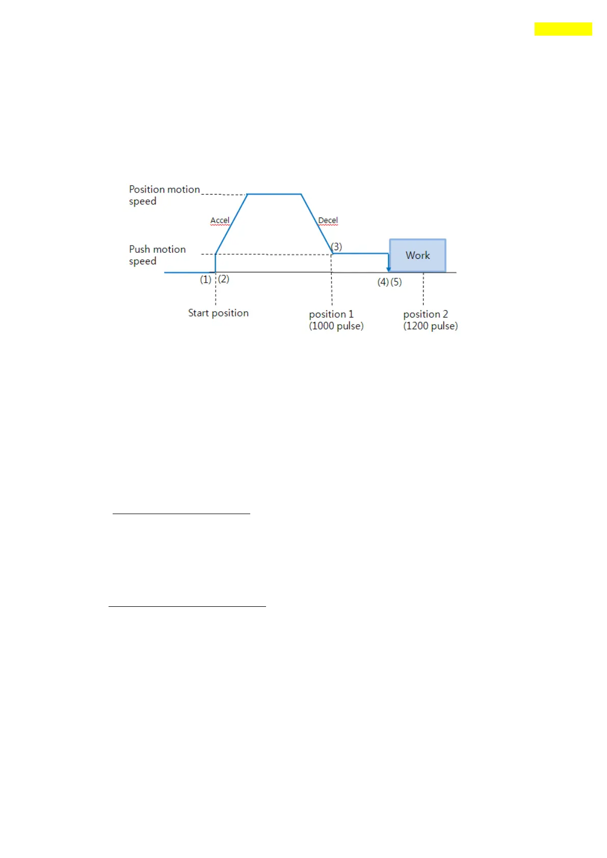
Figure 10.6.1
Start Push Motion command
Normal position motion command is executed.
(status : position mode)
Decelerate the speed from position motion to push motion.
(push motion speed must be lower than 200[rpm].)
④ Push motioning until the work detected with specified motor torque.
(status : push mode)
The motioning will stop just after the work detected.
⑤ When Push mode is ‘Stop’:
After the work detected, the motor will stop but the motor torque will be
maintained and the ‘inposition’/ ‘PT Stoped’/’END’ signal is effective.
The maintained motor torque will be return to normal(Servo ON) status by ‘stop’
command.
(status : release push mode and return to position mode)
When Push mode is ‘Non-stop’:
After the work detected, the motor will not stop and the motor torque will be
maintained and the ‘inposition’and other signal is effective.