www.fastech.co.kr
12. Other Operation Functions
The minimum ‘pulse period’ must set to more than ‘5000[pulse] value.
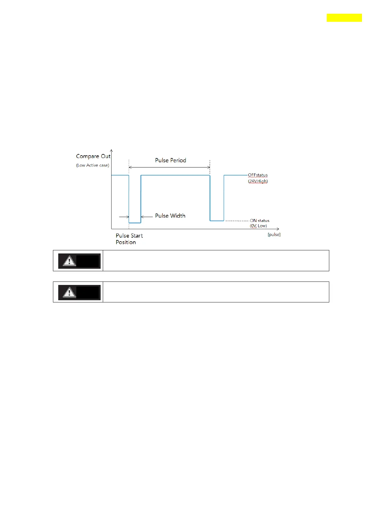
(3) Signal Output
This output pin of CN1 connector for Trigger Pulse is fixed to 「Compare Out」and
the signal diagram is as follows.
The pulse is output only in bigger position area than ‘pulse start
position’and is output in incremental motion direction.
The sign of current position value and the sign of ‘pulse start
position’ must be same to pulse output.
(4) Status Check
By using DLL program, the user can check the trigger pulse output status.
Refer to 「User Manual – Communication Function」.
 Loading...