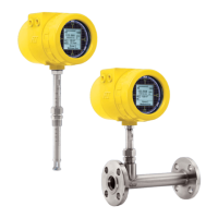
ST100 Series Conguration Software 06EN003403 Rev. C
Fluid Components International LLC iii
Table of Contents
List of Figures
Introduction .......................................................................................................................................................................................................................1
Installation ........................................................................................................................................................................................................................ 1
Running the PC Configuration Application ......................................................................................................................................................................1
Configuration Software Basics ........................................................................................................................................................................................ 3
Password Protection......................................................................................................................................................................................................3
Basic Setup Tab Screens ..................................................................................................................................................................................................4
Advanced Setup Tab Screens ........................................................................................................................................................................................... 7
Configuration Tab Screens ................................................................................................................................................................................................9
Diagnostics Tab Screens ................................................................................................................................................................................................13
Factory Tab Screens ........................................................................................................................................................................................................15
FE1-FE2 Process Data .....................................................................................................................................................................................................18
Parameter Reports .......................................................................................................................................................................................................... 19
Customer Service/Technical Support .............................................................................................................................................................................20
Figure 1 – USB & Ethernet Connectors on Customer Interface Board (Digital Interface Shown) ...................................................................................1
Figure 2 – Welcome Screen .............................................................................................................................................................................................2
Figure 3 – Example Process Data Screen.........................................................................................................................................................................2
Figure 4 – Basic Application Screen Elements ................................................................................................................................................................3
Figure 5 – Example Groups Tab (Basic Setup) ..................................................................................................................................................................4
Figure 6 – Example Units Tab (Basic Setup) .....................................................................................................................................................................5
Figure 7 – Example Pipe Size Tab (Basic Setup) ..............................................................................................................................................................5
Figure 8 – Example Alarms Tab (Basic Setup) ..................................................................................................................................................................5
Figure 9 – Example SD Card Logging Tab (Basic Setup) ..................................................................................................................................................6
Figure 10 – Example Totalizer Tab (Basic Setup) .............................................................................................................................................................6
Figure 11 – Example Pressure Offset Tab (Basic Setup) ..................................................................................................................................................6
Figure 12 – Example User Parameters Tab (Advanced Setup) ......................................................................................................................................... 7
Figure 13 – Example Ethernet Tab (Advanced Setup) ......................................................................................................................................................8
Figure 14 – Example Data and Time Tab (Advanced Setup) ............................................................................................................................................8
Figure 15 – Example Download Calibration Tab (Advanced Setup) .................................................................................................................................8
Figure 16 – Example Reboot Device Tab (Advanced Setup) ............................................................................................................................................9
Figure 17 – Example Output Tab (Configuration) ..............................................................................................................................................................9
Figure 18 – Example 4-20mA User Tab (Configuration) .................................................................................................................................................10
Figure 19 – Example Modbus Tab (Configuration) .........................................................................................................................................................11
Figure 20 – Example Extended Op. Mode Tab (Configuration) .......................................................................................................................................11
Figure 21 – Example Group Switch Setup Tab (Configuration) ......................................................................................................................................11
Figure 22 – Example AST Power Mode Tab (Configuration) ..........................................................................................................................................12
Figure 23 – Example Status Tab (Diagnostics) ............................................................................................................................................................... 13
Figure 24 – Example Fault Log Tab and Example Fault Log List (Diagnostics) ..............................................................................................................14
Figure 25 – Example idR Scheduled Tests Tab and Example idR On-Demand Test Results Display (Diagnostics) ....................................................... 14
Figure 26 – Example idR Test Logs Tab and Example idR Test Log List (Diagnostics) ................................................................................................... 14
Figure 27 – Example Factory Parameters Tab (Factory) .................................................................................................................................................15
Figure 28 – Example Identification Tab (Factory) ...........................................................................................................................................................15
Figure 29 – Example 4-20mA Factory Tab (Factory) .......................................................................................................................................................16
Figure 30 – Example Options Tab (Factory) ....................................................................................................................................................................16
Figure 31 – Example HART Tab (Factory) .......................................................................................................................................................................16
Figure 32 – Example Memory Tab (Factory) ...................................................................................................................................................................17
Figure 33 – Example Reset idRs Tab (Factory) ...............................................................................................................................................................17
Figure 34 – Example Process Data Screen (FE1) ............................................................................................................................................................ 18
Figure 35 – Example Parameter Report, Group 1 ........................................................................................................................................................... 19
Figure 36 – Example Parameter Report, Group 5 ........................................................................................................................................................... 19

 Loading...