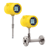
ST100 Series Conguration Software
Fluid Components International LLC 1
Introduction
The ST100 Configuration software is a Windows PC application that lets the user easily set up and configure the ST100 Multipoint Flow Meter prod-
ucts. Use this tool for all instrument commissioning activity. Note that the software application serves both ST100 Series and MT100 product lines.
This manual, however, covers operation with ST100 only (software version 3.1.0.x).
Installation
Find the Software Configurator MSI install file in the Software folder on the product documentation CD or downloaded over the web. The file can be
identified by name – ST MT100 Configurator v3100.msi. Copy this file to a location on your PC designated for ST100 documentation.
Run the MSI installer file (make sure you have administrative rights to install) and follow the on-screen instructions to complete the installation. The
installation process places an application shortcut icon of a stylized meter face on the Windows desktop:
The installer also creates a folder
in the Start Menu named Fluid Components Intl, which contains another program shortcut.
Running the PC Conguration Application
Connect the host PC via USB or Ethernet as required for the application:
• Use Ethernet for remote applications in which the host PC communicates with the instrument over an Ethernet network. Refer to “Advanced
Setup Tab Screens” on page 7 for info on setting Ethernet address values. Connect the instrument to a 100Base-T compatible network
switch or hub using a Cat-5 Ethernet patch cable.
• Use USB for local host PC connection to the instrument. Connect the instrument to the PC USB port using the USB cable provided (Type A to
Type A, male-male; passive, straight-through type).
The ST100 USB and Ethernet connectors are located on the customer interface board as shown in the figure below (remove blind lid for access).
Figure 1 – USB & Ethernet Connectors on Customer Interface Board (Digital Interface Shown)
Note
: To avoid any connection problems make sure the ST100 is fully booted before connecting to the PC USB port and/or launching
the ST100 Configuration software.
Caution
: A host PC connection is intended for temporary use only. Do not make the PC/network connection part of the permanent installation.
Double click the ST100 Configurator icon. The application opens to the Welcome screen as shown in the figure below. Click the appropriate connect but-
ton, USB Connect or Ethernet Connect, at the top of the screen to let the PC communicate with the instrument (with cable connection already made).
ST100 Body
(Blind Lid
Removed)
Customer
Interface
Board
USB Connector
C01264-1-2
Ethernet Connector

 Loading...