FeelTech
FY6600 Series User’s Manual 9
Back Panel Overview
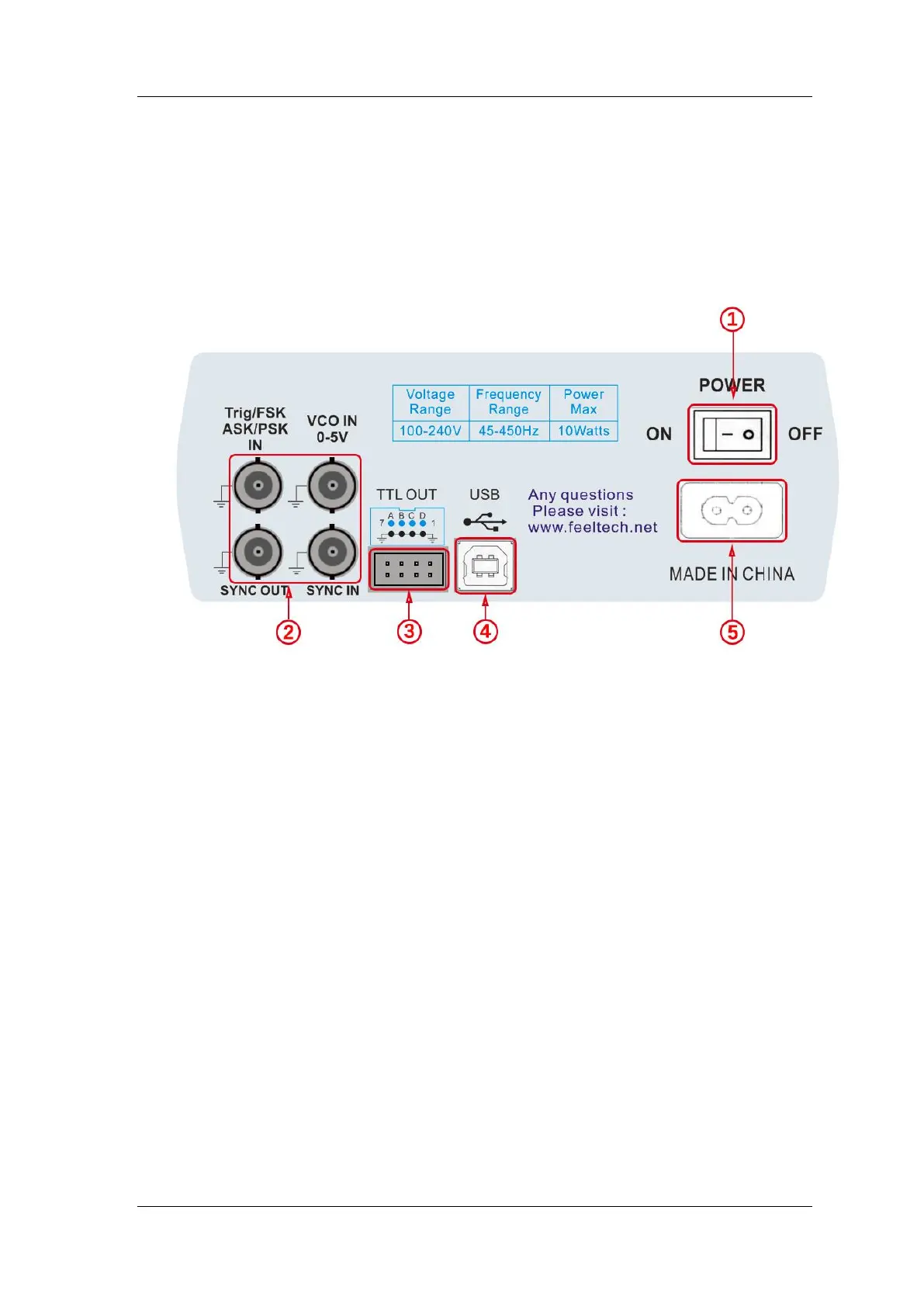
The back panel of FY6600 is as picture 1-2 below. 4 BNC terminals on the
left are DC coupling measuring terminals Trig/FSK/ASK/PSK IN, external sweep
input VCO IN, Synchronization output connector SYNC OUT, and
Synchronization input connector SYNC IN. Then follows TTL output terminal,
USB terminal, power switch and power input socket.
1. Power switch
2. BNC connector
Trig/FSK/ASK/PSK IN: DC coupling measuring terminal and ASK/PSK/FSK
modulation trigger input terminal.
VCO IN: External signal sweep input terminal can realize voltage controlling
frequency, voltage controlling amplitude, voltage controlling offset, voltage
controlling duty cycle and so on. Frequency of external signal input should be
lower than 500 Hz.
SYNC OUT: Synchronization signal output terminal.
SYNC IN: Synchronization signal input terminal.
3. TTL signal output
Frequency of Port A is same with frequency of CH1 output. Frequency of Port B
is same with frequency of Port A but with reverse phase (180°). Frequency of
Port C is same with frequency of CH2. Frequency of Port D is same with Port C
but with reverse phase (180°).
4. USB Device interface
It’s for communication with PC (This is a USB-TTL serial port and driver is
needed). Can programming by host computer.
5. Power input socket(voltage range AC100V-AC240V).
 Loading...