Page. 5
2. Specifications
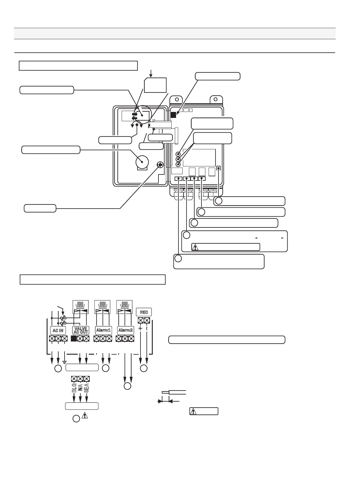
■ 2-3. Internal layout figure and terminal block
Memory card for FOCAS-2000 white or black with marking (circle painted all red)
Improper connection might cause failure.
Peel the wire covering by 5 mm at most.
The wire to be used is AWG12 to 24 or equivalent.
Use AWG16 to 24 or equivalent only for RECout.
SEA
NA
BLG
1
COM
NC
COM
NC
NO
NO
L
N
FG
COM
NC
2
3
4
5
How to connect cables with the terminal block (reference)
1
Output signal for three-way valve (VALVE)
Specification "A" does not have “
NO terminal”.
2
3
4
5
Caution
● For replacement of the memory card, see
"8-8 Replacing the operational log memory."
2-3-1 Inside component layout of FOCAS-2000
● Battery Model CR2450 (lithium battery)
● For replacement of the backup battery, see
"8-7 Replacing the clock backup battery."
● For replacement of the desiccant, see
"8-6 Checkup and replacement timing
of desiccant (silica gel)."
● For replacement of the fuse, see
"8-9 Replacing the fuses."
● All symbol figures of relay show conditions applying current.
● All terminal blocks are removable.
2-3-2 Terminal block and FOCAS-2000 inner connection
Operation record memory
Backup battery for the clock
Reset switch
Desiccant (silica gel)
Fuse for main body
3.15A 1pc
Fuse for valve
2A 2pcs
RECout (output of 4 to 20 mA)
External
output alarm2 signal (Alarm2)
External output alarm1 signal (Alarm1)
Connected to the Power supply source
“Install a power switch externally.”
Connector 2
Connector 1
Light
Dark
LCD contrast
Output signal for the three-way valve
Fuse for valve
2A 2pcs
Caution against the voltage
Alarm1 signal
Alarm2 signal
External output
External output
RECout (output
of 4 to 20 mA)
AC power
1. Single-wired cables are recommended.
2. Loosen the screw with a flat-head screwdriver, insert a cable,
and then tighten the screw.
3. Connecting work is possible with the terminal block being removed
(the terminal block is removable type).
4. The relays with the cables being connected are installed
on the terminal block.
5 mm or less
● Use (or press) this when the machine is frozen and cannot be recovered.
Caution
Voltage output
Specification A
Specification B
AC IN
VALVE
AC OUT
Alarm1 Alarm2
REC