79
EN
cod. 3542B380 - Rev 00 - 05/2022
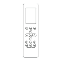
2. Secure the back panel directly to the wall or to 2- or 3-module junction boxes using the screw seats, making sure
torunthewiresthroughtheslotasindicateding.7.
g. 7
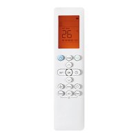
3. Make the electrical connections following the connection diagram
g. 8
NOTES For the device to function correctly, the power supply provided must be used.
For the correct modbus connection it is advisable to use shielded twisted cables suitable for RS485
transmission with section not less than 0.34 mm
2
.
For the power supply, do not use cables with section less than 0.5 mm
2
Do not use cables longer than 25 m.
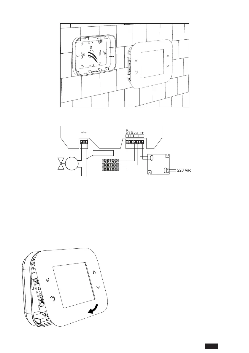
4. Bringthefrontpaneltothewallplatebyrstmatchingthetwocatchesatthetopwiththeseatsonthebackpanel.
5. Press the lower part of the panel until it is completely closed and secured.
g. 9
NOTE
If properly closed you should hear a click.

 Loading...