EasyManua.ls Logo

ferrotec CARRERA - User Manual

ferrotec CARRERA
57 pages
Print Icon
To Next Page IconTo Next Page
Loading...
Operation manual
High-voltage power supply unit
Type: CARRERA
Serial no:
FERROTEC GmbH
Postfach 33
Seerosenstraße 1
72669 Unterensingen
Telefon: +49 7022 - 9270-0
Telefax: +49 7022 - 9270-10
Internet: www.ferrotec-europe.com
E-Mail: ebgun@de.ferrotec.com Version 1.3_15
Translation of the original Operation manual

Questions and Answers

  • S
    sandraperezAug 3, 2025
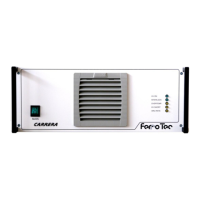
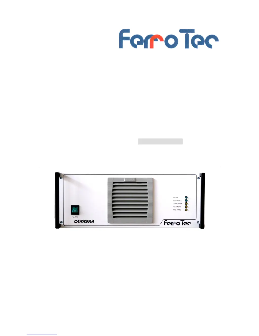
    What to do if the ferrotec CARRERA cannot be switched ON?
    • D
      Dale LewisAug 3, 2025
      If your ferrotec Power Supply does not switch on, check the following: * Ensure the mains plug is properly connected. * Verify the high-voltage connector is connected and locked. * Confirm that all safety conditions are met by checking the safety interlock circuit.
  • A
    Andrew CampbellAug 10, 2025
    Why is the “ARC rate” LED lit on my ferrotec CARRERA Power Supply?
    • V
      Victoria BrownAug 11, 2025
      The “ARC rate” LED might be lit on your ferrotec Power Supply due to: * Process pressure being too low: use a lower process pressure. * ARC rate exceeding the set limit: change the ARC rate setting.
  • W
    William GreenAug 18, 2025
    What to do if the “Over-temperature” LED is lit on ferrotec CARRERA?
    • V
      Vicki CurryAug 18, 2025
      If the “Over-temperature” LED is lit on your ferrotec Power Supply, the cause may be a dirty filter mat, in which case you should replace the filter mat. If the fan is not operating, contact the FERROTEC Service Dept.
  • D
    Donald LarsonAug 25, 2025
    What to do if the “HV short” LED is lit on ferrotec Power Supply?
    • T
      Tammie PhillipsAug 26, 2025
      If the “HV short” LED is lit on your ferrotec Power Supply, this indicates a short circuit. You should clean the electron beam vaporizer.

Summary

2 Overview and Intended Use

2.1 Overview CARRERA-System

Provides an overview of the CARRERA system components.

2.2 Intended Use

Details the specific applications and purpose of the HVP unit.

2.3 Explanation of terms

Defines key abbreviations and terms used in the manual.

2.4 Technical specifications

Lists detailed technical parameters and data for the unit.

3 Safety

3.1 Notes; Explanations

Explains the meaning of various safety symbols and warnings.

3.1.1 Explanation of used safety symbols

Details specific danger and notice symbols used in the manual.

3.1.2 Machine Identification

Describes how to identify the machine using its serial number.

3.2 Integrated Safety Systems

Covers the safety systems integrated into the unit.

3.3 Overview of electrical connections

Illustrates front and back panel connections and ports.

3.4 Safety Precautions (by the Operator)

Outlines operator responsibilities for safe operation and handling.

3.5 Responsibilities of the Operator

Details operator duties and legal compliance for safe operation.

3.6 Safety Inspections and Tests

Lists factory and in-term inspections and tests required.

4 General Warnings

4.1 Dangers

Highlights critical dangers such as electric shock and burns.

4.2 Operating Areas and Danger Zones at the Machines

Defines operational areas and safety zones around the equipment.

4.3 Operating and Maintenance Personnel

Specifies qualifications and responsibilities of personnel.

4.4 Spare and Wearing parts

Discusses the use of original vs. non-original parts and repairs.

4.5 Shutdown Procedure

Provides step-by-step instructions for safely shutting down the unit.

5 Installation

5.1 Delivery package

Lists the items included in the product delivery package.

5.2 Transport and Packaging

Instructions for receiving and inspecting shipments.

5.3 Intermediate Storage

Guidelines for storing the unit before installation.

5.4 Transportation to the point of Installation (by Operator)

Procedures for moving the unit to its installation location.

5.5 Assembly, Installation (only for trained personnel)

Guides assembly and initial start-up by trained personnel.

5.5.1 Assembly

Instructions for mounting the unit, e.g., in a 19"-Rack.

5.5.2 Electric Connection

Details the requirements and steps for electrical connection.

5.5.3 Overview of the electrical connectors and fuses

Identifies and explains rear panel connectors and fuse blocks.

5.5.4 Connection of the high-voltage power supply unit

Guides connection of HV cable, earthing, control, and mains lines.

6 Functional description

6.1 Putting in operation for the first time (for specialized personnel only)

Procedures for initial system start-up by qualified personnel.

7 Operation

7.1 Operation and displaying elements

Identifies and explains front panel controls and status indicators.

7.2 Operation modes

States that operating modes are in separate instructions.

7.2.2 Switching on

Step-by-step guide for powering on the system.

7.2.3 Switching off

Provides instructions for safely powering down the unit.

8 Cleaning;Maintenance

8.1 Cleaning Procedures

Covers daily and monthly cleaning tasks.

8.3 Maintenance Tasks

Outlines maintenance, testing, and inspection procedures.

9 Troubleshooting

10 Emergency

11 Dismantling;Disposal

Dismantling Procedures

Outlines safe dismantling by skilled personnel.

Disposal Guidelines

Provides instructions for environmentally sound disposal.

12 Appendix; Options

12.1 Appendix 1; Control unit GENIUS

Details about the GENIUS control unit and its functions.

12.2 Appendix 2; Filament Power Supply FPS

Details about the Filament Power Supply FPS.

ferrotec CARRERA Specifications

General IconGeneral
Brandferrotec
ModelCARRERA
CategoryPower Supply
LanguageEnglish

Related product manuals