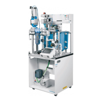
Technical data Filtration Learning System
18 © Festo Didactic 696684
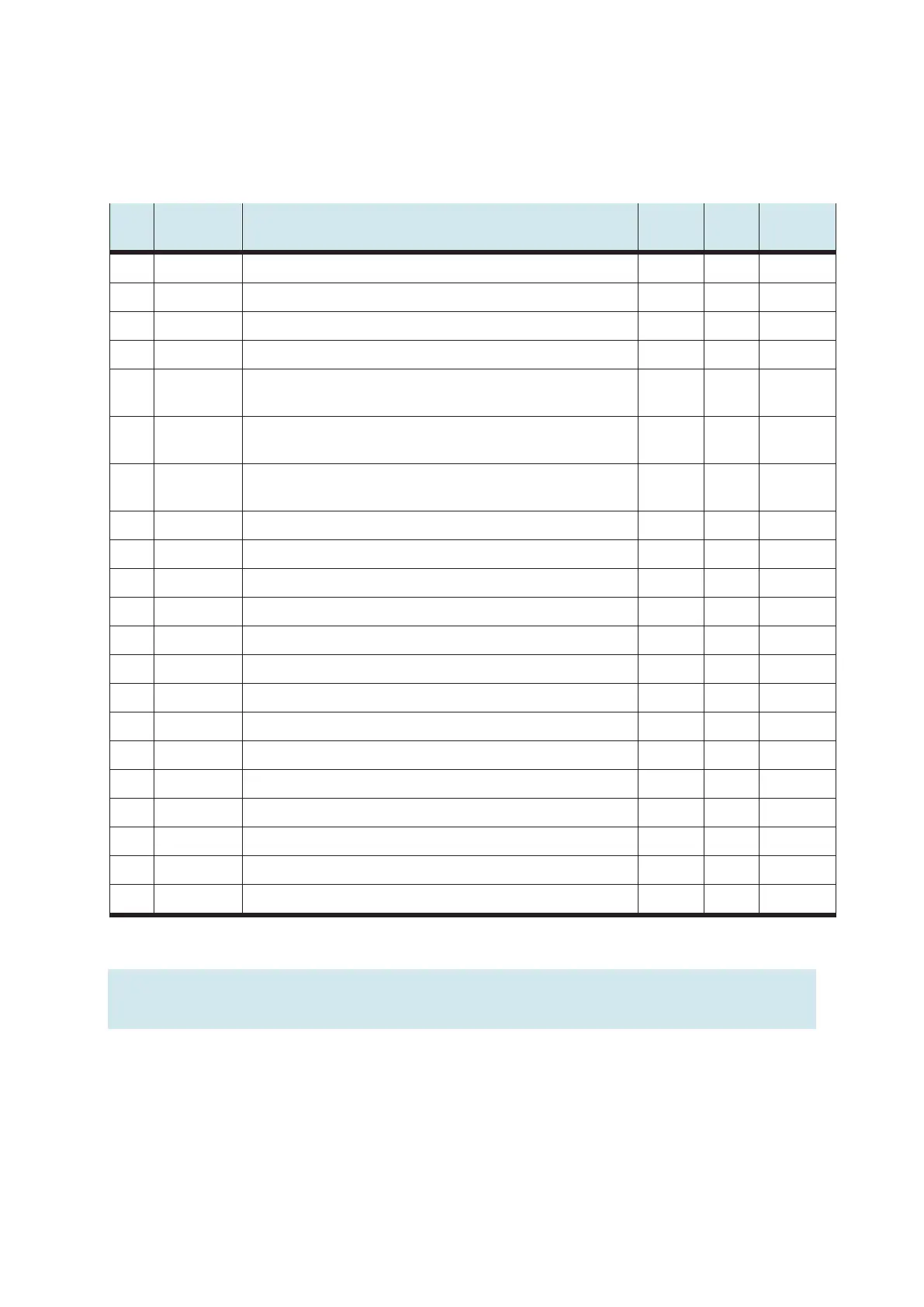
6.2 Pin allocation table
6.2.1 Digital terminal
I/O Reference
designation
Designation Terminal SysLink
Pin
SysLink
Wire color
I0 -BP1_GW Limit pressure sensor, blow-out pressure OK 9 13 Gray-pink
I1 -BG2 Capacitive proximity sensor, upper limit level of waste water tank VA1 10 14 Red-blue
I2 -BG3 Capacitive proximity sensor, lower limit level of waste water tank VA1 11 15 White-green
I3 -BG4 Capacitive proximity sensor, upper limit level of process water tank VE2 12 16 Brown-green
I4 -BG5
Capacitive proximity sensor, lower limit level of process water tank VE2
13 17 White-
yellow
I5 SG6_BG7 Micro switch for sensor box, butterfly valve AF3 opened /
Reed switch for the gate valve SM2 closed
14 18 Brown-
yellow
I6 SG8_BG9 Micro switch for sensor box, butterfly valve AF3 closed /
Reed switch for the gate valve SM2 opened
15 19 White-gray
I7 -KF10 Overflow alarm of the relay contact, collection error 16 20 Gray-brown
Q0 -MB1 Valve ON, activate exhaust pressure 1 1 White
Q1 -MA2 Motor pump PL1 ON, waste water 2 2 Brown
Q2 -MA3 Motor pump PL2 ON, downstream station 3 3 Green
Q3 -KF4 Relay ON, gate valve SM2, opening / butterfly valve AF3 CLOSING 4 4 Yellow
Q4 -MB6 Open 3W ball valve VV6, in position downstream station 5 5 Gray
Q5 -MA7 Motor AG4 stirrer ON 6 6 Pink
Q6 7 7 Blue
Q7 8 8 Red
24 V A 24 V power supply for outputs 24 VA 9+10 Black
24 V B 24 V power supply for inputs 24VB 21+22 White-pink
GND A 0 V power supply for outputs GND A 11 Brown-pink
GND A 0 V power supply for outputs GND A 12 Purple
GND B 0 V power supply for inputs GND B 23+24 White-blue
Note
Cable jumpers are connected from emergency off to bit 1.5 on all preferred PLC versions.