Technical data Filtration Learning System
20 © Festo Didactic 696684
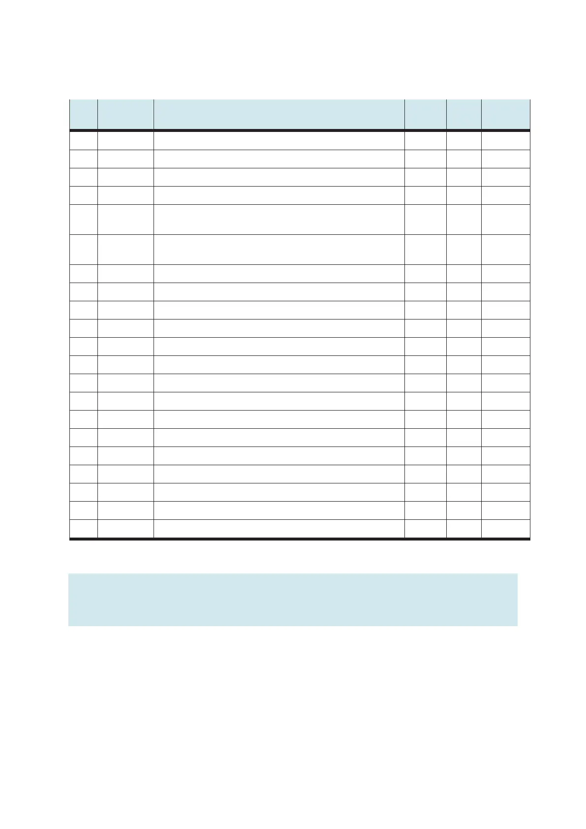
6.2.3 Control panel
I/O Reference
designation
Designation Terminal SysLink
Pin
SysLink
Wire color
I0 -SF1 START button 13 Gray-pink
I1 -SF2 STOP button (NC contact) 14 Red-blue
I2 -SF3 AUTO/MAN key switch 15 White-green
I3 -SF4 RESET button 16 Brown-green
I4 I4 Communication input I4 17 White-
yellow
I5 I5 EMERGENCY STOP (NC contact) 18 Brown-
yellow
I6 I6 Communication input I6, downstream station process ready 19 White-gray
I7 I7 Communication input I7 20 Gray-brown
Q0 -PF1 Indicator light START 1 White
Q1 -PF2 Indicator light RESET¶ 2 Brown
Q2 -PF3 Indicator light function Q1 3 Green
Q3 -PF4 Indicator light function Q2 4 Yellow
Q4 Q4 Communication output Q4, station ready for process 5 Gray
Q5 Q5 Communication output Q5 6 Pink
Q6 Q6 Communication output Q6 7 Blue
Q7 Q7 Communication output Q7 8 Red
24 V A 24 V power supply for outputs 9+10 Black
24 V B 24 V power supply for inputs 21+22 White-pink
GND A 0 V power supply for outputs 11 Brown-pink
GND A 0 V power supply for outputs 12 Purple
GND B 0 V power supply for inputs 23+24 White-blue
Note
Communication input I5 is used as an EMERGENCY-STOP signal input in PLC EduTrainers.
The inputs and outputs of the control panel are located on the second byte of the EduTrainer.