4 Electrical installation
Festo – GDCP-CMMP-M0-HW-EN – 1511c – English 43
PE
BR-CH
BR-INT
ZK+
ZK
-
L
N
24V+
GND24V
X9
Single-phase
L
N
0 V
PE
+24 V
PE
BR-CH
BR-INT
ZK+
ZK
-
L
N
24V+
GND24V
X9
Single-phase
Power circuit
breakers
Power circuit
breakers
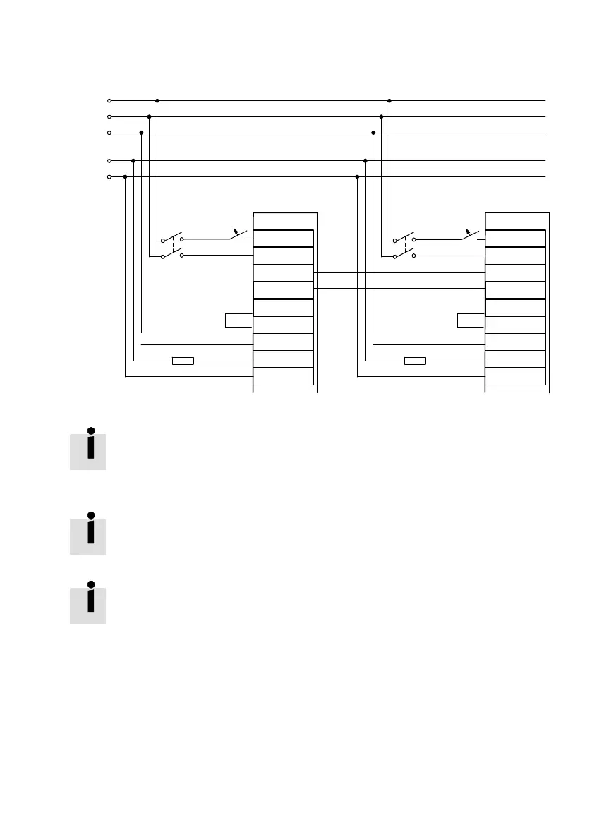
Fig. 4.6 Example of intermediate circuit coupling with common supply, single-phase
Fig. 4.6 is a schematic representation; note the information for mains fuses in
è Section 4.8.4.
4.8.6 Braking resistor
If no external braking resistor is used, a bridge to the internal braking resistor must be
connected in order for the intermediate circuit quick discharge to function! è Tab. 4.17 or
Tab. 4.18.
For larger braking power an external braking resistor must be connected [X9]
è Section 4.7.2 and Fig. 4.5.
The motor controller detects the external brake resistance automatically as soon as the intermediate
circuit voltage rises above the response threshold (è A.1, Tab. A.6).
After that, a connected external brake resistance can also be displayed in the configuration software.

 Loading...