Festo Controller CECC
29
4.4 Configuring the I/O interface
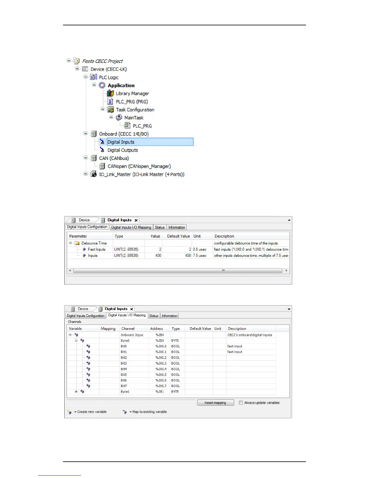
1. Highlight the "Digital Inputs" or "Digital Outputs" interfaces under the "Onboard" branch in the
CODESYS V3 pbF device window.
Figure: Device window - Onboard I/O interface
2. Double-clicking the highlighted interface "Digital Inputs" opens a new tab in the editing window for
configuring the inputs of the I/O interface.
Settings for the debounce time for the inputs of the I/O interface can be found on the "Digital Inputs
Configuration" sub-tab.
Figure: Digital inputs I/O configuration
3. Click the "Digital Inputs I/O Mapping" sub-tab to show the current values for the inputs.
Figure: Digital inputs I/O mapping
4. Double-clicking the interface "Digital Outputs" opens the corresponding tab in the editing window for
configuring the outputs of the I/O interface.