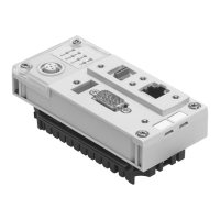
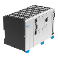
Do you have a question about the Festo CECC-X-M1 series and is the answer not in the manual?
Observe safety instructions in corresponding chapters; special regulations before task instructions.
Control documented is for installation in machines or automated systems in industrial environments.
Personnel must be qualified specialists familiar with electrical control technology and safety regulations.
Instructions for inserting and securing the product onto an H-rail.
Steps to remove the product from an H-rail using a clip and connector.
Procedure for drilling holes and securing the product to a flat surface.
Steps to remove the product by loosening mounting screws.
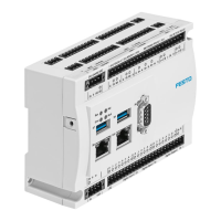
Details on digital input/output interfaces X2, X3, X4, including terminal functions and specifications.
Pinout and comments for the CANopen interface CAN 1 (X6).
Details on USB interfaces X7 and X9, supported functions, and limitations.
Details on CANopen interface CAN 2 for motor controllers, including terminal functions.
Details on digital input terminals X17, connection technology, and sensor configuration.
Pinout and comments for the CANopen interface CAN 2 (X18).
Details on analogue input terminals X19, connection technology, and signal resolution.
Details on digital output terminals X20, connection technology, and output circuitry.
Details on supported MicroSD cards and functions like boot projects and data storage.
Explains remanent variables and their storage capacity on the controller.
Details vibration and shock load severity levels (SL1, SL2) with corresponding parameters.
| Number of digital inputs | 8 |
|---|---|
| Short circuit strength of outputs | Yes |
| Number of analogue inputs | 2 |
| Number of counter inputs | 2 |
| CANopen interface | Yes |
| Ethernet interface | Yes |
| Web server | Yes |
| PLC functionality | Yes |
| Degree of protection | IP20 |
| Current consumption | 500 mA |
